Hi Guys,
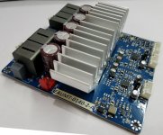
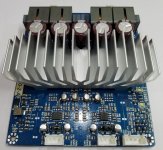
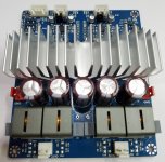
Glad to share your guys with my customized DIY design - TPA3251 Amplifier Board for DIY Application.
this AMP and SMPS were released to my friends a few months ago and also have been used into their project successfully.
As your guys already know,the TPA32xx series chip have a lots of improvements,it features an advanced integrated feedback design and proprietary high-speed gate driver error correction to allows ultra low distortion. it attract many DIYer to start his own design to enjoy the excellent performance and also more and more companies have involved this chip into their product.
Key Features of My Design
Full Project Detail:TPA3251 2ch PurePath™ Ultra-HD Class D Audio Amplifier
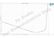
Performance Measurements Detail:
Audio Performance Measurements_EAUMT-0140-2-A
Audio Performance Measurements_TPA3251D2EVM
Audio Performance Measurements_TPA3251D2EVM_vs_EAUMT-0140-2-A
Glad to share your guys with my customized DIY design - TPA3251 Amplifier Board for DIY Application.
this AMP and SMPS were released to my friends a few months ago and also have been used into their project successfully.
As your guys already know,the TPA32xx series chip have a lots of improvements,it features an advanced integrated feedback design and proprietary high-speed gate driver error correction to allows ultra low distortion. it attract many DIYer to start his own design to enjoy the excellent performance and also more and more companies have involved this chip into their product.
Key Features of My Design
- Enhanced design with very low output noise (62uV/A-weighted) and lower THD+N (0.0015%/20W/4ohm)
- Fully differential layout design for better noise cancellation
- Smaller and Compact size(105mm*90mm*36.5mm – L*W*H)
- Additional power ON/OFF reset circuit for Pop noise suppression
- BTL configuration only for best audio performance
- Single supply voltage range 24V~36 V(UVP:24V)
Full Project Detail:TPA3251 2ch PurePath™ Ultra-HD Class D Audio Amplifier
Performance Measurements Detail:
Audio Performance Measurements_EAUMT-0140-2-A
Audio Performance Measurements_TPA3251D2EVM
Audio Performance Measurements_TPA3251D2EVM_vs_EAUMT-0140-2-A
Attachments
Looks really nice, so might as well ask the obvious question: Are you selling pcbs/kits/boards?
/U.
I'm interested too!
Looks really nice, so might as well ask the obvious question: Are you selling pcbs/kits/boards?
/U.
There's a "buy it now" button on the webpage that hasn't yet been activated.
I don't recall the button being there yesterday...
Nice design.
What DCDC-buck you're using, an LMR16(14)006? I had some race-conditions with the TPS3802 when using speed-up-caps and high power output.
sorry,i don't understand you mean : race-conditions?
the DCDC is set down from 36V,so how can it related to reset part?
Looks really nice, so might as well ask the obvious question: Are you selling pcbs/kits/boards?
/U.
I'm interested too!
yes,i am planning to but there are only a few pieces boards remain.
i will post it on ebay to have a try.
sorry,i don't understand you mean : race-conditions?
the DCDC is set down from 36V,so how can it related to reset part?
I found the behaviour of the UVP/Reset-Circuit rather sensitive to short power peaks, additionally the power-down sequence where not reliable. Further investigation showed that this is related to the lower feedback-voltage of the LMR16006 compared to the "ancient" buck controller used with the EVM.
i had posted it on ebay,any one can try if you are interesting.
http://www.ebay.com/itm/332129205164?
http://www.ebay.com/itm/332129205164?
Last edited:
I'm interested in seeing your grounding-scheme.(Regarding output filter loop and frontend section)
You may share?
Hi Doc.
had you read ti slaa719 app note?
i didn't follow all but keep the similar way,keep the analog front section Ground
separately with DC-DC/Logic control sections.
for the output stage,i just route them in differential way.
i can share you the layout if you give me a private email.
Hi mate,
yes i know this slaa719, followed it as well but found some interesting effects while doing performance tests. Still unsure where there's magnetic coupling, thats why i've asked.
Please see pm.
Regards,
doc
Doc.
i didn't met the magnetic coupling in my board.
also i just sent the layout i did in my project to your email.
any questions,please feel free to let me know.
- Status
- This old topic is closed. If you want to reopen this topic, contact a moderator using the "Report Post" button.
- Home
- Amplifiers
- Class D
- TPA3251 2Ch Amplifier Board DIY Design (Compact size/Amazing Performance)