Hi,
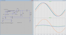
i'm designing a class d amplifier with current feedback as in figure below.

with the following features:
Vbus=50V
Iout programmable from 100mA to 1Arms
Vout=35Vrms max
When the load overcomes the programmed current (i.e. 1Arms) the amplifier saturates and the sinusoidal output becomes a square wave output. For example i want to transmit on 1200 ohm a 35Vrms sinusoidal voltage even though the current feedback is not locked.
So my purpose is to mantain a maximum allowable voltage on the output.
Is it possible to obtain that feature? A second feedback is needed?
Could you help me?
Thanks.
Attached Thumbnails
i'm designing a class d amplifier with current feedback as in figure below.
with the following features:
Vbus=50V
Iout programmable from 100mA to 1Arms
Vout=35Vrms max
When the load overcomes the programmed current (i.e. 1Arms) the amplifier saturates and the sinusoidal output becomes a square wave output. For example i want to transmit on 1200 ohm a 35Vrms sinusoidal voltage even though the current feedback is not locked.
So my purpose is to mantain a maximum allowable voltage on the output.
Is it possible to obtain that feature? A second feedback is needed?
Could you help me?
Thanks.
Attached Thumbnails
The feature you described is nonlinear.
You basically need 2 diodes (or transistors in common base configuration) from Rsense to integrator. (And the forgotten resistor from Vin to integrator.)
In order to vary current limit a variable gain should be inserted after Rsense.
Don't write RMS! This limit current should not be time-dependent (since you wrote square wave output) so RMS is meaningless/misleading.
The characteristics will not be perfect, limit current will not be exact, or limiting will not happen instantly.
Could you explain me better how to connect 2 diodes? Do you mean OR configuration?
Shouldn't 2 diodes limit the sinusoid to only half wave?
In order to program output current I have thought to do with input signal. So for 1Vpp input sin there will be 1A output current set. I don't know if it is the right way.
Let me know.
Thanks
Shouldn't 2 diodes limit the sinusoid to only half wave?
In order to program output current I have thought to do with input signal. So for 1Vpp input sin there will be 1A output current set. I don't know if it is the right way.
Let me know.
Thanks
Then I dont know what you want.
If output current is proportional to the input voltage, then no saturation, no square wave until the voltage limit is reached, but you wrote
35V/1200ohm=30 mA, which is not inside your specified 100mA and 1A limit.
Think over what you really want!
If output current is proportional to the input voltage, then no saturation, no square wave until the voltage limit is reached, but you wrote
This is meaningless, in case of controlled current load cannot "overcome the current". In case of a voltage controlled current generator the voltage can be limited, but this happens automatically at the power supply voltage.When the load overcomes the programmed current (i.e. 1Arms)
For example i want to transmit on 1200 ohm a 35Vrms sinusoidal voltage
35V/1200ohm=30 mA, which is not inside your specified 100mA and 1A limit.
Think over what you really want!
I try to explain my idea.
Vbus=50V
Iout programmable from 100mA to 1Arms
Vout=35Vrms max
PWM switching=200khz
Output frequency 3KHz-20KHz
I want to realize a voltage controlled current source.
In my application the maximum pwm duty is 90%.
So i can generate sinusoids from 50V/sqrt(2)*0.01 to 50V/sqrt(2)*0.9.
Setting gain in the proper way i want that with input signal of 2*0.85Vpp (i forgot that the triangular wave for the comparator is 2Vpp) there is a 1Arms current set on the output. So with a input signal of 2*0.085Vpp there will be a 0.1Arms set.
That approach works for LOAD higher than the maximum set. So i can regulate 1Arms on 30 OHM up to 1 OHM. But if my load becomes 300 OHM the input amplifier (integrator) saturates.
I hope this helps you to understand and advise me on the right way. Perhaps i'm forgetting something in feedback loop scheme.
Let me know.
Last edited:
OFF: So you call 1 ohm higher than 30. Its OK when you explicitely state this usage of terminology, but should be avoided saying it and expecting others will understand the same way.
And inside the described circuit nothing is programmable, so in connection with it please don't say current is programmed, because it is misleading. Input signal is generated by a programmed device, this is the correct statement.
ON:
Now I understand what you need generally, but some details are missing:
- What is the freq dependancy of load impedance? Constant? Capacitive? Inductive? Variable? Unknown? The required feedbacks depend on this strongly.
- With what accuracy you want to control the current on load at different frequency?
- What ripple current/voltage is allowed?
Depending on the required accuracy and the range of load impedances this task can easily become impossible. The more you limit the possible impedances and the more deviation is allowed (especially at high freq) the more likely that it is possible.
An AC voltage feedback from output is most likely needed. More details can be given only after load specification.
Last edited:
Unfortunately 10% for 1 ohm to 100 ohm at 20 kHz is already somewhere around (or above) the highest possible accuracy in this topology and with this operating frequency. Only if you could adaptively set control loop for the actual load then you could reach higher.
And even this limit is only possible to reach with relatively high power loss on Rsense in case of low load resistance. Is this acceptable for you?
And even this limit is only possible to reach with relatively high power loss on Rsense in case of low load resistance. Is this acceptable for you?
Yes.
Could you suggest me, or send in private, a possible scheme from witch to start with my studies? Do you have a tutorial or application notes on this subject?
At the moment the accuracy is not a problem.
Thanks
I will try to find time for drawing a schematic. The basic is not much more than yours, only an RC feedback is missing from output voltage, series resistor on input, and an inductor would help in series with load.
Last edited:
Maybe is an old thread of me interesting for you:
http://www.diyaudio.com/forums/class-d/228641-insod-amp-2.html
http://www.diyaudio.com/forums/class-d/228641-insod-amp-2.html
Maybe is an old thread of me interesting for you:
http://www.diyaudio.com/forums/class-d/228641-insod-amp-2.html
It is very interesting and seems that the second amplifier has current and voltage control.
Do you have ltspice files?
Do you remember another useful information?
Seems that the current feedback and voltage feedback are connected at the same node. How do you calculate components values?
Thanks let me know.
Youre welcome!
But at second thought it would be better using current mode PWM control right in the first (or only?) control loop.
It is very straightforward.
Determining L: it should provide 1.4 Ap with some margin at 20 kHz on 50 V peak sinusoidal voltage. Therefore L=50V/2A/20kHz/2/pi=200 uH.
Feedback of PWM:
It should be PI type. (Type II in other terminology.). P component can be determined by the requirement that voltage slope must always be slower than the slope of triangle. Feedback is a current controlled voltage source. (How to make it in real life is a question left later.)
V/I_P<(2Vpp/2us)/(100V/200uH)=1V/us /
0.5A/us=2ohm, but in order to maintain margin I would choose 1 ohm.
To be continued...
Last edited:
Without any I(ntegrating) feedback component loop gain is
G(s)=RP*Gpwm/(L*j*s+Rl)
Where Gpwm=100V/2V=50, RP is the transresistance of P(roportional) component of feedback, and Rl is load resistance.
For maintaining 10% amplitude accuracy you need 2...9 of loop gain depending on the phase angle. I will try setting phase angle close to 90 degree, so maybe |G|=2 will be enough. (Very optimistic assumption.)
At 20 kHz lets solve |G|=2 for Rl, to find the highest possible load resistance that is still controllable!
To be continued...
- Status
- This old topic is closed. If you want to reopen this topic, contact a moderator using the "Report Post" button.
- Home
- Amplifiers
- Class D
- class d amplifier current output