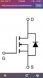
Can two N- Mosfets with pretty close specs be interchanged. The main difference is one uses internally or it's symbol shows a regular diode across Drain and Source, instead of a zener diode? What will happen when swapped? What will also happen if a lower spec N-Mosfet is upgraded to higher numbers/specs such as below part#s?
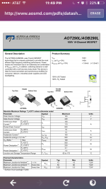
Ex.: Irf540 drop swap with AOT290L
Ex.: Irf540 drop swap with AOT290L
What will also happen if a lower spec N-Mosfet is upgraded to higher numbers/specs such as below part#s?
Ex.: Irf540 drop swap with AOT290L
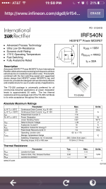
The die size difference between these two parts is rather large, shown by the disparity in the power dissipation specs. So with the higher current part come much higher capacitances, which in a switching application will most likely be significant.
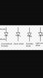
The symbol you see is not a zener but a Schottky diode.
Hmmn.... zener and schottkey's still really look a little different. Here....
Attachments
The die size difference between these two parts is rather large, shown by the disparity in the power dissipation specs. So with the higher current part come much higher capacitances, which in a switching application will most likely be significant.
Thanks for the response. I was expecting the answers/responses to be along the lines of , "loud sound then blow up" or "distortion (clamping)".
My original thoughts were that if (you're) upgrading a Mosfet with 3x (the Wattage for example), you'd have 3x lifespan or power handling capability as opposed to just one. This is the same logic that i've always had as my answer "or repair solution for good" to those amps that are constantly driven to the max. I dont mean like a "cheater" amp but an amp that will last 3x longer!
Its a narrow way to consider the issue, only focusing on the FET itself running cooler (which is true, but only in isolation). Designs are not just the linear sums of their parts, change one part and it'll affect the operation of others.
If you swapped FETs for devices with much higher capacitances in a classD amp, you stand quite a good chance of blowing up the whole thing due to the dead-time no longer being as designed, leading to potential shoot-through and rapid self-destruction.
If you swapped FETs for devices with much higher capacitances in a classD amp, you stand quite a good chance of blowing up the whole thing due to the dead-time no longer being as designed, leading to potential shoot-through and rapid self-destruction.
Semiconductors should essentially be failure proof in a good and well designed application. Failure is almost always caused by a problem not related to the semiconductors themselves.
The reverse connected diode is simply an unavoidable function related to the construction of the FET (although it can be useful and thus made use of in some applications as it can handle high currents).
The reverse connected diode is simply an unavoidable function related to the construction of the FET (although it can be useful and thus made use of in some applications as it can handle high currents).
Kinda like putting a truck motor in a sports car. The rest of the vehicle was designed for a sports car motor, why would you put in a truck motor?
Kinda. But actually not. The reason for changing FET was clear. No reason to compare it to nonsense.
IRF540 and IRF540N are also different devices. IRF540 alone covers many different devices (significantly different capacitance specs along different manufacturers). So what we are comparing to what? And for what aspect?
AOT290L has big input capacitance but negligible feedback capacitance. Qg total is not significantly larger than one of the IRF540N. Telling "much higher capacitances" is simply not true.
AOT290L has big input capacitance but negligible feedback capacitance. Qg total is not significantly larger than one of the IRF540N. Telling "much higher capacitances" is simply not true.
Thanks for the response. I was expecting the answers/responses to be along the lines of , "loud sound then blow up" or "distortion (clamping)".
I like that one.

My original thoughts were that if (you're) upgrading a Mosfet with 3x (the Wattage for example), you'd have 3x lifespan or power handling capability as opposed to just one. This is the same logic that i've always had as my answer "or repair solution for good" to those amps that are constantly driven to the max. I dont mean like a "cheater" amp but an amp that will last 3x longer!
If you change the FET (characteristics, different capacitance, the AOT290 got the 5x the input and output capacitance) you can mess up filters and feedback, the needed dead time (like abraxalito already mentioned), the rise and fall time (on/off) is important, if the dead time is too short, the FETs have to cope with much higher currents and losses, the power supply is put under strain ofcourse then too.
You might put a lot of stress on other components, like the driver IC or the output filter, power supply or cause phase change.
The car comparison wasn't that wrong. If you change the engine, it might run much longer. But then maybe it breaks the clutch. Or transmission. Or drivetrain. Or, or, or.. It has to fit together.
If you want to make the amp foolproof and indestructible, you have to improve the whole amplifier, not only one thing. This way you are only shifting the point of failure to something else, which might break much easier with the change. And how it really changes depends very much on the circuit, you cannot switch one thing to 'improve' it, a lot of things are tied together. You cannot tell at all the amp will 'live' 3x longer (or longer at all!) if you cange the MOSFETs.
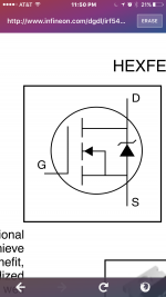
MOSFET body diodes are excellent zeners with huge power handling capability and quite steep avalanche characteristics.
Interesting - so how to know what the breakdown voltage is when its not shown in the DS? Also what's the temperature coefficient of the breakdown voltage?
AOT290L has big input capacitance but negligible feedback capacitance. Qg total is not significantly larger than one of the IRF540N.
Taking IR's datasheet as reference, roughly double the Qg at 10V enhancement and 50V for Vds. (46nC vs 88nC) 'Not significantly larger' is simply propaganda.
Interesting - so how to know what the breakdown voltage is when its not shown in the DS? Also what's the temperature coefficient of the breakdown voltage?
Almost all MOS-FETs (lets say 98%) have zener diode integrated on chip and it's breakdown voltage is slightly above maximum rated voltage of device, for example 50V MOS-FET have zener around 55V.
I didn't test those breakdown voltage vs temperature but I guess that is projected on such way that for full specified temperature range breakdown voltage will not drop below maximum specified working voltage of MOS-FET.
Without such zener diode, many DC/DC converters will never reach working life longer than few microseconds, they protect MOS-FET from over-voltage spikes, mainly caused by driving heavy inductive load.
Thanks for that - as designer though I'd not want to exceed the rated voltage of the FET in the DS so I'd use an external device to limit the maximum drain voltage. Allowing voltage excursions above the rating (to 55V for a 50V FET as in your example) must surely have some impact on long term reliability?
- Status
- This old topic is closed. If you want to reopen this topic, contact a moderator using the "Report Post" button.
- Home
- Amplifiers
- Class D
- Interchangeable mosfets?