Actually it is very easy game.
If you want over load protection at the situation, it is very simple, put thermal switch on the heatsink. Finish your problem, not my problem.
I only consider high possibility to happen, not all bad things. I know what you mean. But I don't consider that as that is no way someone to turn on the amp with no signal but have bad luck with output shorted. A double jeopardy.
Hi,hi pafi will this circut work comfortable with +/- 85vlts with a 2ohms load ?? outputs fets are irfb4227
85V and 2 ohms is possible for irfb4227, but no headroom, and there is no protection in this sch, and
- I can't find the gate driver PSU (not on schematic)
- bootstrap voltage is not hold correctly during positive overdrive. 3 ms max, it is dangerous.
- turn on is very slow. Good enough only for bass.
- clipping point is much lower for negative.
- Opto pairing is not indicated. :-(
- offset voltage setting is terrible.
should I continue checking it?
The OT posts have been removed, and kartino has been given a 50-point infraction for being disrespectful to the other members.
How about Pafi?
He started right?
niceI am waiting a fairness
If not.... sorry I am done with this forum
Hi,
85V and 2 ohms is possible for irfb4227, but no headroom, and there is no protection in this sch, and
- I can't find the gate driver PSU (not on schematic)
- bootstrap voltage is not hold correctly during positive overdrive. 3 ms max, it is dangerous.
- turn on is very slow. Good enough only for bass.
- clipping point is much lower for negative.
- Opto pairing is not indicated. :-(
- offset voltage setting is terrible.
should I continue checking it?
yes i would really appeciate that , because according to the author this circuit is compatible with many different fets
yes i would really appeciate that , because according to the author this circuit is compatible with many different fets
What does it mean? It works the same terrible way with any of them?
Why do you care a dangerous and bad quality design with missing parts? The one in the first post of the topic http://www.diyaudio.com/forums/class-d/166214-ucd-25-watts-1200-watts-using-2-mosfets.html is much better!
Last edited:
What does it mean? It works the same terrible way with any of them?
Why do you care a dangerous and bad quality design with missing parts? The one in the first post of the topic http://www.diyaudio.com/forums/class-d/166214-ucd-25-watts-1200-watts-using-2-mosfets.html is much better!
thanks sir pafi for the quick reply .i wanted to use ir2110 , irfb4227 fets at +/-80vlts at 2 ohms . i wanted an effecient stable design which will not fry the fets for no reason.
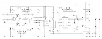
o.k then is this tekkos design with two lm311 nice ??
Attachments
thanks sir pafi for the quick reply .i wanted to use ir2110 , irfb4227 fets at +/-80vlts at 2 ohms . i wanted an effecient stable design which will not fry the fets for no reason.
o.k then is this tekkos design with two lm311 nice ??
Not really. The feedback is inefficient, it has visible distortion. No protection, high DC offset, etc...
Chocoholic had a public design. I am sure it is 10 times better.
Not really. The feedback is inefficient, it has visible distortion. No protection, high DC offset, etc...
Chocoholic had a public design. I am sure it is 10 times better.
please post chocoholics scheme sir. does it use available components???
have a look at his threadplease post chocoholics scheme sir. does it use available components???
http://www.diyaudio.com/forums/class-d/255046-systemd-liteamp.html
thanks voltwide and paffi
paffi i tried and made several versions of ucd25-1200w circuits they are stable and reliable . but the issue comes when you mount more than 1 in a amplifier casing there is a noise which is hard to get rid off
i wanted to use lm311 ,ir2110 and irfb4227 because of availability and price . and i have a few parts with me
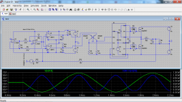
o.k then can this circuit by ssassen work nicely at +/-80volts using lm311 as comparator ,irfb4227 as output fets??
http://www.diyaudio.com/forums/class-d/58476-my-non-discrete-sodfa-class-d-amp.html
http://www.diyaudio.com/forums/class-d/58476-my-non-discrete-sodfa-class-d-amp-14.html
paffi i tried and made several versions of ucd25-1200w circuits they are stable and reliable . but the issue comes when you mount more than 1 in a amplifier casing there is a noise which is hard to get rid off
i wanted to use lm311 ,ir2110 and irfb4227 because of availability and price . and i have a few parts with me
o.k then can this circuit by ssassen work nicely at +/-80volts using lm311 as comparator ,irfb4227 as output fets??
http://www.diyaudio.com/forums/class-d/58476-my-non-discrete-sodfa-class-d-amp.html
http://www.diyaudio.com/forums/class-d/58476-my-non-discrete-sodfa-class-d-amp-14.html
Attachments
Stewin,
So you have a problem with interference. UcD is definitely more sensitive for this than clocked or pre-filter feedback designs, but still I don't think the solution should be the trial of randomly selected other circuits. UcD is sensitive because of the relatively low switching residual on comparator, and because of post-filter feedback, but this is also the reason of the high performance.
The interference you hear is caused by bad PCB layout, coupled power supplies, wrong wiring, common/floating heatsinks, or open cores.
As soon as you eliminate all of the problems above you will have an interference-free amp no matter what schematic you use.
Learn designing high speed, Low EMI PCB first!
The first key is GND plane. Second is SMD.
When you reduced the interference to a low but still audible level, you can cheat a little: synchronize them! This converts whistle interference to distortion, this is why I suggest to do this only when it is almost eliminated.
There is a mistake in the schematic. Is there only one? Maybe.
(First opa feedback is not connected to opa out, but to GND.)
thanks paffi for the quick reply ,let me perfect on designing high speed, Low EMI PCB . hopefully i,ll design a custom board for discreet ucd i found it sounding the best except layout issues.
Attachments
hi all this videos can be helpful https://www.youtube.com/results?search_query=designing+high+speed,+Low+EMI+PCB+
hi all this videos can be helpful https://www.youtube.com/results?search_query=designing+high+speed,+Low+EMI+PCB+
Well, unfortunately most techniques mentioned here are specially related to impedance matched signalling. ClassD amp is not that high freq.
- Home
- Amplifiers
- Class D
- Fullbridge Class D PA ultra high power