Hello to every lucky follower of this Class-D section of the DIY Audio forum.
I come in peace from the Switching Tubes Valley.
After the landing at the Burning Amp 2016,
the Switchinglow Project is now here
for all the brave DIYers that would like to catch
the challenge of exploring a New World.
Between 2008 and 2015 I developed a reliable method
to use tubes as switching power devices in class-D
amp circuits.
I've called this method AmpDiVa technology, where
AmpDiVa means Amplificatori Digitali Valvolari,
or Digital Tubes Amplifiers.
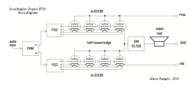
The AmpDiVa tech uses:
- vacuum tubes as switching power devices in the arms
of a full or half H bridge circuit
- tubes can be connected in parallel on each arm
in order to achieve higher output current
- the tubes on each arm are switched by each own
Floating Grid Driver circuit that applies,
between grids and cathodes,
negative pulses to obtain the off state of the tube
and
positive pulses to push the tube in an high conduction state,
according to a PWM scheme provided by a Pulse Width Modulator
- Signal Integrity methods are used to timing the tubes set
(this is not mandatory, it's an option)
The Switchinglow Project is an evaluation module
proposed to the DIYers that would like to explore
the AmpDiVa method starting from a reliable, affordable
and user friendly platform.
This is the EVM block diagram.
Further readings and info can be found
in my web pages www.switchinglow.com
As this here under frame says,

don't hesitate to ask for any questions !
Marco Rampin
(*) I've found this gentle frame hanged up on the engine room
of the WWII ship Jeremiah O'Brien moored in San Francisco
I come in peace from the Switching Tubes Valley.
After the landing at the Burning Amp 2016,
the Switchinglow Project is now here
for all the brave DIYers that would like to catch
the challenge of exploring a New World.
Between 2008 and 2015 I developed a reliable method
to use tubes as switching power devices in class-D
amp circuits.
I've called this method AmpDiVa technology, where
AmpDiVa means Amplificatori Digitali Valvolari,
or Digital Tubes Amplifiers.
The AmpDiVa tech uses:
- vacuum tubes as switching power devices in the arms
of a full or half H bridge circuit
- tubes can be connected in parallel on each arm
in order to achieve higher output current
- the tubes on each arm are switched by each own
Floating Grid Driver circuit that applies,
between grids and cathodes,
negative pulses to obtain the off state of the tube
and
positive pulses to push the tube in an high conduction state,
according to a PWM scheme provided by a Pulse Width Modulator
- Signal Integrity methods are used to timing the tubes set
(this is not mandatory, it's an option)
The Switchinglow Project is an evaluation module
proposed to the DIYers that would like to explore
the AmpDiVa method starting from a reliable, affordable
and user friendly platform.
This is the EVM block diagram.
Further readings and info can be found
in my web pages www.switchinglow.com
As this here under frame says,
don't hesitate to ask for any questions !
Marco Rampin
(*) I've found this gentle frame hanged up on the engine room
of the WWII ship Jeremiah O'Brien moored in San Francisco
Theoretical there is not too much wrong with the idea save, voltage drop across the triodes is high and power dissipation will be excessive. there are only two ECC99 on each side, not four. A pair Power Moss Fets would be a much better idea and it is tried and tested.
Thank you Jon for your interest.
The above block diagram is not a full electric diagram, so the tubes are simply
pictured as single triode. Each ECC contains two triodes, and in the circuit
they are connected in parallel, so each side of the bridge has really 4 tubes for a total of 8 triodes.
Of course even if using positive grid polarization, the anode-cathode impedance of a triode can not compete with the Rds-on of a modern power semiconductor, that is in the order of few milliohms.
Further, there is also the power to light the heaters, so the power efficiency of the system can not be comparable at all with a semiconductors bridge !
No doubt MOS do it better !
From a mere efficiency point of view, there is no any reason to adop this method.
The main reason to consider is because it seems to be unusual, it seems enough challenging to explore.
Excessive power dissipattion have to be limited by at least three factors:
- positive grid polarization
- power supply rail voltages
- load + EMI filter impedance
The good news is the power supply voltages could be very low compared to
the voltages used in linear tube amplifiers.
Here a +/-12Vdc is enough for having a clear sound on the speaker.
The prototype at the BA'16 was running at +/-35Vdc on two series connected speakers for a total of 16 ohm load.
The AmpDiVa Accademia prototypes shown at the European Maker Faire 2015 and 2016 ran on +/-75Vdc, 24 ohm load.
And in both case the tubes were running steady quiet and warm for hours, without any excessive power dissipation.
- Status
- Not open for further replies.