Here is a sticky for us. Switching range is a measure for, how much Class-D a Class-D amplifier really is.
Class-D is Class-B with Pulse Width Modulation. Pulse width shall go with signal. Because actors are inert, minimum pulse width and so minimum PWM-transferred amplitude are limited. Between lo and hi signal limit lies Switching Range Fswitching (F for factor), which can be calculated as the inverse of the product of 2Pi, power actor time constant (which is time for output power to reach half of full power) and pulse width modulation frequency. With a modulation frequency of 300KHz and a power actor time constant of 5ns we obtain Fswitching=40dB.
Below switching range, the amplifier must try to work in unmodulated fashion. Actors tend to ignore small inputs, hence crossover distortion appears. But we can feed back. As loop gain at fmodulation is -1 (oscillation), feedback cannot be stronger than fmodulation divided by fsignal. We set closed loop gain to 1 and obtain a feedback range Ffeedback of 40dB for a signal of 3KHz.
Intermediate dynamic range Fintermediate is Fswitching+Ffeedback=80dB. Ncore is optimized for this.
Another means is idle current, size of which should be somewhere between signal currents at lo limits of Fintermediate and Fswitching. With a maximum current of 20A, we need an idle current inbetween 2mA to 200mA. Abletec does it like this.
An alternative is feedforward. Adding a lo voltage amplifier, which outputs virtual ground, on which the error of the Class-D one appears, we can also overcome distortion. Devialet use feedforward.
I hope, that this helps.
Last edited:
Are you trying to tell us that you can detect crossover distortion at 400kHz+?
Class D is on or off. That is it is operating in class C. Class C is off until switched on. The crossover distortion you speak about is not distortion, it is dead time that is needed to avoid both output FETs to be on at the same time by allowing time for the Gate - Drain capacitances to discharge.
Class D is on or off. That is it is operating in class C. Class C is off until switched on. The crossover distortion you speak about is not distortion, it is dead time that is needed to avoid both output FETs to be on at the same time by allowing time for the Gate - Drain capacitances to discharge.
It is crossover distortion at 4KHz and below, what bothers me -- theoretically, as i have not conscientously heard it in a Class-D amplifier.
Class C is single-ended, used with narrow bandpasses for producing a single radio frequency. Class-B is symmetrical, say push-pull, as needed for at least moderately efficient generation of hi bandwidth signals.
Dead Time is practically the opposite of idle current. If one analyses good Class-D circuits of the feedforward-less flavour, one will see that they do not have any Dead Time, but rather both power actors do conduct a bit at the same time.
Last edited:
...
If one analyses good Class-D circuits of the feedforward-less flavour, one will see that they do not have any Dead Time, but rather both power actors do conduct a bit at the same time.
A large (although narrow) current spike?
Sounds inefficient.
Any examples we could look at?
I wrote "a bit", not "large". If power actor gates are fed by the raw (only Ugs- and Ig-limited) PWM signal, and some idle current runs thru them, then there is no Dead Time.A large (although narrow) current spike?
The latter. Below switching range, output stages of Class-D and Class-A/B work the same way. In fact, one can run any Class-A/B amplifier as Class-D: Just add a PWModulator frontend, a lowpass backend and modify feedback. Depending on fmodulation it may run hot already in idle state, because the output stage is not up to the task, but there is no principal difference.
The whole thread is total junk. For "switching range" Grasso gives different definitions every time (in different topics and forums), but none of the definitions are correct and disambigous. At this time his mistic "power actor time constant" become "time for output power to reach half of full power". This is alone a complete mess, since the output power changing speed of a ClassD amp is not related to the switching device, but the filter. So "output power" must be a mistake. But what power could he really meant? I dont know, but very probably he dont know either. An other problem is in the time, since he only mentioned 1 point, the end, but what about the start?
There are many more similarly false and/or meaningless statements and bad terminologies in this topic, but correcting or falsifying them needs much time (simply because they are soo many), and I see zero valuable information here, so my advice is to close or abandon this mentally harmful thread, not to infect our minds.
There are many more similarly false and/or meaningless statements and bad terminologies in this topic, but correcting or falsifying them needs much time (simply because they are soo many), and I see zero valuable information here, so my advice is to close or abandon this mentally harmful thread, not to infect our minds.
So for "idle current" do you mean the 1-100uA of D-S leakage or some larger value as a result of the device not being fully turned off?
The latter....
So if you don't turn the device fully off intentionally is it still considered Class D?
Wouldn't it be class A (by definition)?
Running a class A amplifier as a PWM source seems inefficient to me.
Any examples we could look at?
Last edited:
Abletec amplifiers are Class-D on top of Class-A/B.So if you don't turn the device fully off intentionally is it still considered Class D?
Wouldn't it be class A (by definition)?
If you can obtain schematics for Abletec amplifiers, have a look.Any examples we could look at?
I do not think so. Class-D means to pulse power. The smaller desired signal, the shorter pulse. (A different scheme would be "the smaller desired signal, the lesser pulses", and in fact this is being done, called "adaptive modulation for lowest sideband noise" or so.) But minimum pulse length is limited by inertia. Hence classic Class-D has a lower operational limit. As it also has an upper operational limit, it has an operational range, which i coined Switching Range, just as with mechanical gear.Pafi said:At this time his mistic "power actor time constant" become "time for output power to reach half of full power". This is alone a complete mess, since the output power changing speed of a ClassD amp is not related to the switching device, but the filter. So "output power" must be a mistake.
...
Hence classic Class-D has a lower operational limit.
...
What do you mean by "classic Class-D"? Pulse Width Modulation?
What do you mean by "lower operational limit"? Negative rail voltage?
What do you mean by "upper operational limit"? Positive rail voltage?
So you are saying that the output of a class D amplifier is limited to the supply rails.
I totally agree.
Not many class AB or even class A amplifiers can do that. (to the best of my knowledge)
Last edited:
If you do not like discussing your writings you'd better blog.I do not answer these questions, because thou are pulling things out of context, DUG. Thou may be that stupid or only pretend to be, but there is no sense argueing with someone argueing like that.
Btw, your statements do not make much sense for me.
I have a problem simulating Class-D:
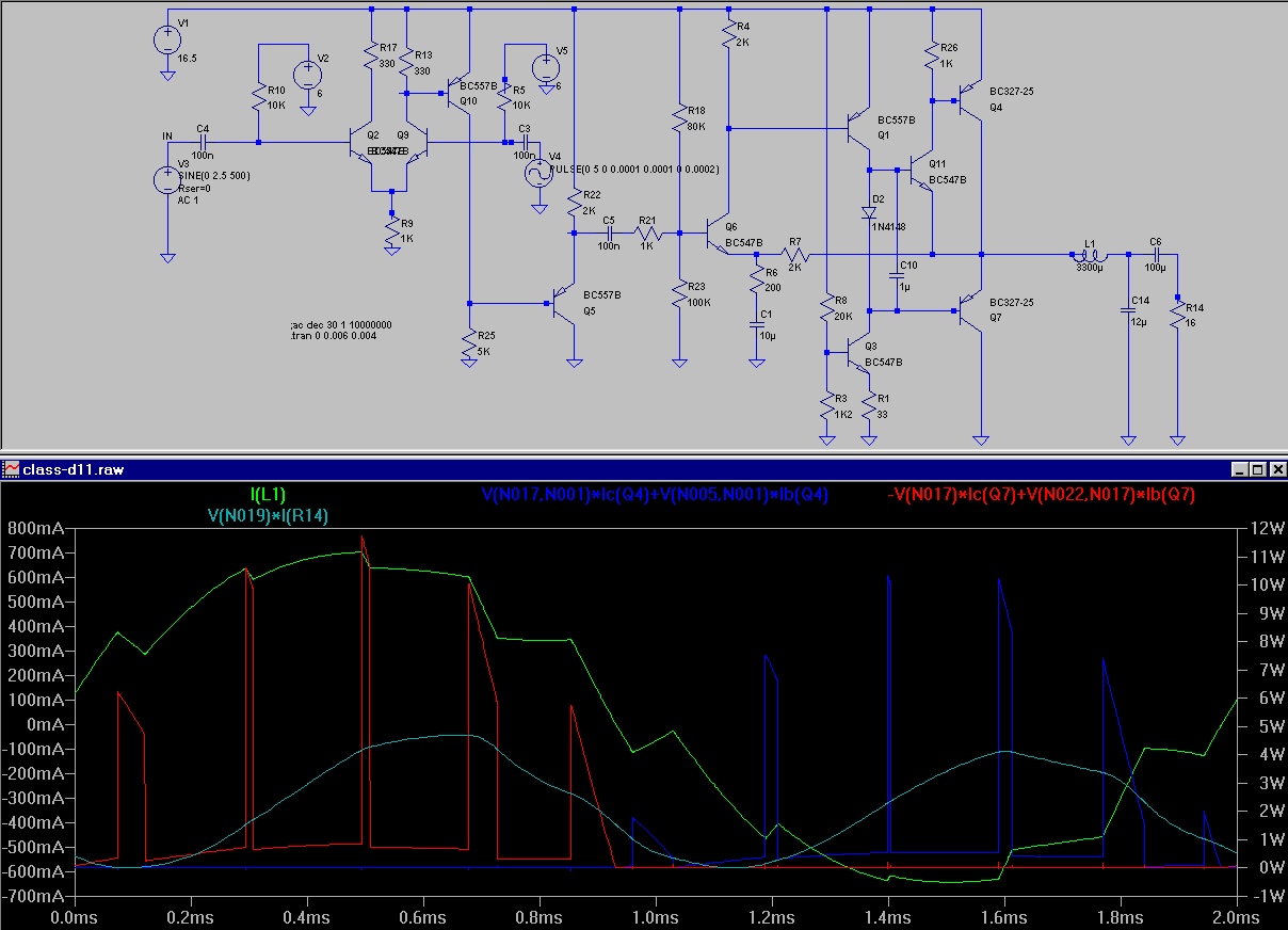
Voltage at output of power transistors follows input computed by pulse width modulation, xcept for small glitches. But current thru output inductor is a partial average of voltage --is voltage not derivation of current for inductances, and current derivation of voltage for capacitances, for sinus is derivation of cosinus, and cosinus derivation of sinus?. Since current stays positive, when voltage is negative, and vice versa, much power is lost in transistors. Only remedy is to remove output filter. But then, how can all that switching stuff work?
Voltage at output of power transistors follows input computed by pulse width modulation, xcept for small glitches. But current thru output inductor is a partial average of voltage --is voltage not derivation of current for inductances, and current derivation of voltage for capacitances, for sinus is derivation of cosinus, and cosinus derivation of sinus?. Since current stays positive, when voltage is negative, and vice versa, much power is lost in transistors. Only remedy is to remove output filter. But then, how can all that switching stuff work?
Attachments
Last edited:
You are using an RC to generate a "sort of" triangle or sawtooth waveform for the comparator stage. When you have no feedback loop around the comparator circuit this waveform shape is much more critical.
I would also up the switching frequency to above 50KHz. (IMHO) Your ratio of switching frequency to "af" frequency is very low. 12:1 ? 11:1 ?
I am not sure why you are using what looks like a linear amplifier for the output stage.
Perhaps some of your filtering takes place there rather than the LC on the output.
DUG,
triangle is accomplished by "pulse" signal. I would flesh this out with hysteresis,comparator,integrator loop.
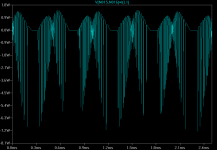
I started with tweetier filter and self-oscillating 64KHz:

but soon noticed the power loss problem. As i was unsure of the reasons, i switched to slower frequencies and dedicated comparator.
For sake of understandability i draw discrete, bipolar transistors from start to end. Power ones preferably PNP, which are faster than NPN. I draw the amplifier, which had the largest swing.
The problem i asked you about is simulation:

An inductance can not loose real power and so heat up. Power is complex, hence we need two plots to show it. Sticking to LTspice symbols, we would plot real (heat) and imaginary power. Alternatively we could plot norm and phase.
triangle is accomplished by "pulse" signal. I would flesh this out with hysteresis,comparator,integrator loop.
I started with tweetier filter and self-oscillating 64KHz:
but soon noticed the power loss problem. As i was unsure of the reasons, i switched to slower frequencies and dedicated comparator.
For sake of understandability i draw discrete, bipolar transistors from start to end. Power ones preferably PNP, which are faster than NPN. I draw the amplifier, which had the largest swing.
The problem i asked you about is simulation:
An inductance can not loose real power and so heat up. Power is complex, hence we need two plots to show it. Sticking to LTspice symbols, we would plot real (heat) and imaginary power. Alternatively we could plot norm and phase.
Attachments
Last edited:
The power loss reason is Gegeninduktion. The choke tries to keep up norm and sign of its current, which so still flows thru the now "off" transistor. Also for that reason many power transistors include clamping diodes, sometimes Zener ones, which also limit forward voltage.
But an amplifier with feedback never switches off output transistors but tries too keep source impedance low, even at clipping point, so diodes intended to clamp never get to do so.
But an amplifier with feedback never switches off output transistors but tries too keep source impedance low, even at clipping point, so diodes intended to clamp never get to do so.
The explanation is simple: these are not ClassD amplifiers. Details: the transistor you want to switch off can not switch off, because there is no current path to commutate the current to.
There is a good reason why 99% of the ClassD amps use MOSFET output stage: the channel can conduct both current direction at high intensity. A bipolar transistor needs reversed base current to be able to conduct reversed current, but in your schematic this is not provided at the neccessary level.
Good to see you finally decided to start dealing with ClassD amps, but I suggest you to start with a simple and real one.
The simplest ClassD amp doesn't contain more than 2 MOSFETs and 8 passive components.
Please learn English and please try to be specific! Some of your sentences are very hard, sometimes impossible to decode.
Obviously this is false in case of ClassD (due to its definition). I don't have a clue what you wanted to say really.
But an amplifier with feedback never switches off output transistors
Obviously this is false in case of ClassD (due to its definition). I don't have a clue what you wanted to say really.
- Status
- This old topic is closed. If you want to reopen this topic, contact a moderator using the "Report Post" button.
- Home
- Amplifiers
- Class D
- Switching Range