")
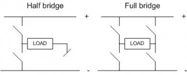
Both driver the transformer flux in both directions, so the transformer utilization is higher.
The half bridge has only 1/2 the voltage swing of a full bridge, hence the transferred power relative to transistor VDS rating is not as good.
The half bridge is not suitable to current mode control, as it will walk the center point to one rail or the other.
Both the half bridge and full bridge, to take full advantage of the extended transformer range (using flux in both directions, must have some kind of flux balancing of the volt seconds in each direction. For the full bridge, this is provided automatically by current mode control. For the half bridge, the most common approach is capacitive coupling of the transformer, and derating the flux swing.
The full bridge can be adapted into a very efficient converter known as the Zero Voltage Switching Phase shift converter; each side of the bridge is driven by what is essentially a square wave, and the relative phase shift of the square waves is adjusted to control the transfered power. Typical controller is UCC3895., from TI.
The half bridge is typically in competition with the two transitor forward converter, which has similar transistor and driver count and voltage, but only drives the transformer flux in one direction, so it has a somewhat larger transformer, but can use current mode control with it's benefits. Two transistor forward converters have been used up to 1-2 KW, though usually in that range the Bridge supply in some variant is employed. Sometimes two two transistor forward converters are run together in an interleaved mode. Transformer is larger than for the bridge, but flux balancing isn't a concern, nor current mode slope compensation to prevent instability when net PWM duty cycle is over 50%.
Different tradeoffs for different applications.
~Jon
JonMarsh said:Both driver the transformer flux in both directions, so the transformer utilization is higher.
The half bridge has only 1/2 the voltage swing of a full bridge, hence the transferred power relative to transistor VDS rating is not as good.
The half bridge is not suitable to current mode control, as it will walk the center point to one rail or the other.
Both the half bridge and full bridge, to take full advantage of the extended transformer range (using flux in both directions, must have some kind of flux balancing of the volt seconds in each direction. For the full bridge, this is provided automatically by current mode control. For the half bridge, the most common approach is capacitive coupling of the transformer, and derating the flux swing.
The full bridge can be adapted into a very efficient converter known as the Zero Voltage Switching Phase shift converter; each side of the bridge is driven by what is essentially a square wave, and the relative phase shift of the square waves is adjusted to control the transfered power. Typical controller is UCC3895., from TI.
The half bridge is typically in competition with the two transitor forward converter, which has similar transistor and driver count and voltage, but only drives the transformer flux in one direction, so it has a somewhat larger transformer, but can use current mode control with it's benefits. Two transistor forward converters have been used up to 1-2 KW, though usually in that range the Bridge supply in some variant is employed. Sometimes two two transistor forward converters are run together in an interleaved mode. Transformer is larger than for the bridge, but flux balancing isn't a concern, nor current mode slope compensation to prevent instability when net PWM duty cycle is over 50%.
Different tradeoffs for different applications.
~Jon
My past SMPS work experience must be similar to yours. I've seen a method for using current mode with the half-bridge topology, to keep the balance. Seemed overly complicated for what you get. I like peak and average current mode, so I tend to stay with the forward, full-bridge, and push-pull. The Zero Voltage Switching Phase Shift Converter is a great way to go for medium-high and high power.
Slope compensation works, but puts the roll-off between 1 and 2 poles, partially negating the benefits of current mode. Even with this, I still prefer current mode in most cases.
I'm not a big fan of the 2 transistor forward converter. For low power, I like the one transistor forward converter without the reset winding. I prefer an RC snubber and zero voltage switching-off. This has pretty decent efficiency, but I agree with you about it not having great transformer utilization.
I agree - lots of trade-offs.
I have a question about power supply pumping in a full bridge.
I have only seen it mentioned in a presentation by IRC. at
http://www.irf.com/product-info/audio/classdtutorial.pdf on page 13.
My question is this:
On the first have cycle the current flow from the supply through the load (and its respective LC filters) and then to ground. On the next half cycle the current direction in the load can not change instantaneously because of the L's in the LC filters. So the current now flow from ground up through the load (and it respective LC filters) and up to the battery.
Isn't sending current back to the batter a BAD thing, especially if your battery is not rechargeable?
Can you also point me to references about power supply bus pumping.
- Status
- This old topic is closed. If you want to reopen this topic, contact a moderator using the "Report Post" button.
- Home
- Amplifiers
- Class D
- Whats the difference between full bridge and half-bridge SMPS ?