hi which caps do you mean?
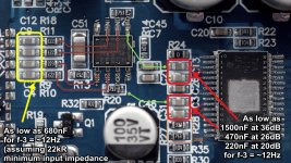
Are you going to keep the 5532 Diff2SE opamp stage? If yes, then
If you remove the Diff2SE opamp, then the values marked in RED apply for the caps marked in YELLOW. (As the red ones get removed when bypassing the opamp stage)
Values are calculated for f(-3B)cut-off at 12Hz.
Attachments
... Excessive popping is due to the capacitance value of the dc-blocking-caps when their bias-voltage is removed.
On a TPA3116 2.1 module, I found that removing the PS Bypass caps solved the turn off popping. I put them upstream of the power-on switch. My theory, without the bypass caps, there isn't any stored energy to create a pop when the supply voltage drops to where the amp is unstable.
The pop is due to imbalance on the inputs when the powersupply collapses. That's why there's /SDZ and /MUTE available to the system integrator.
Pop-Issues are also fixed by this litte circuit:
TPA3132D2 Simple Antipop Schematic – #360customs
Pop-Issues are also fixed by this litte circuit:
TPA3132D2 Simple Antipop Schematic – #360customs
Are you going to keep the 5532 Diff2SE opamp stage? If yes, then

If you remove the Diff2SE opamp, then the values marked in RED apply for the caps marked in YELLOW. (As the red ones get removed when bypassing the opamp stage)
Values are calculated for f(-3B)cut-off at 12Hz.
ok thanks for that, i think i will leave the Diff2SE opamp as it is.
so i need to change the yellow once with 680nF and the red once with either 1500, 470 or 220nF ? but how do i know which i should take?
The standard config on these boards is 36dB for the TPA3116, so 1500nF is needed. In most cases 20dB is more than enough, which can be achieved by removing R27 "753". After gain is reduced, 220nF is okay here.
Another mod is to change those 4 "753" resistors around the 5532 for "223" (75k -> 22k) to bring down the gain to 1.
You may try this in combination with changing the yellow caps to 680n.
Another mod is to change those 4 "753" resistors around the 5532 for "223" (75k -> 22k) to bring down the gain to 1.
You may try this in combination with changing the yellow caps to 680n.
The standard config on these boards is 36dB for the TPA3116, so 1500nF is needed. In most cases 20dB is more than enough, which can be achieved by removing R27 "753". After gain is reduced, 220nF is okay here.
Another mod is to change those 4 "753" resistors around the 5532 for "223" (75k -> 22k) to bring down the gain to 1.
You may try this in combination with changing the yellow caps to 680n.
ok thanks for clearing that up. i will order the right caps and try it.
Another mod is to change those 4 "753" resistors around the 5532 for "223" (75k -> 22k) to bring down the gain to 1.
This refers to the gain of the Diff2SE stage. (not the TPA3116)
Okay today I played around with the AUX input a bit. Actually it turned out to be pretty easy.. I enabled one PIO input, set "USB AUDIO ALWAYS ROUTED" (Dont know if that is needed) and the Inputs began working. Setting a user event for Wired input seemed to make no difference.
I learned the Volume level of the AUX in is related to the A2DP Default volume level which is a bit of a bummer since I set it low to make the audio tones a reasonable level, but with it low, the AUX input is very quiet. setting to 15 makes the AUX level much more reasonable but still not as loud as the BT audio.
But all of this is a bit unimportant because the original issue of popping when the unit shuts down the AMP seems to still be there- So I am guessing that its not because the amp is shutting down, its more to do with the Muting process... and Amplifier gain as you mentioned previously. Im thinking the next step is removal/ bypass of the components you mentioned for the preamp.
Project for a later day....
Do you mind sharing a screenshot, or giving info on how you enabled the one PIO input? I've finally got my board all wired up, but haven't been able to get the AUX in enabled yet.
Side question, has anybody been able to change or upload their own voice prompts? I am pretty sure I have bricked a module or two attempting to do so, but I really want to get it working. I am using the configuration tool and created a wav file with similar settings to the example audio, but no luck.
I have a similar module but it runs the CSR 64215 and PCM5102a.
I bought it hoping it would not suffer the usual problems of popping and hissing but it makes a slight hiss for a few seconds after you stop playing music - then goes quiet.
It makes a small pop when you start playing any input again.
I'm running 48 ohm headphones but I've tried feeding it to line-in on my PC and it has the same issue.
Is there any way to fix this board? I found and attached a PDF showing how they wired it.
They somehow managed to get the left and right channels swapped on the design, even though the channels appear to be correctly routed between the DAC and the headphone socket.
Attachments
About AUX input commutation to avoid POP noise
Hi guys!
I'm new in this forum. In first place let me thank you for all your valuable work and information.
I'm working on a project with a module using the CRS8635 and have the same problem about the pop noise when audio streaming stops.
I reached this forum and found the activation of the AUX input as a very clever and smart solution.
I've tried it with, unfortunately, no success. It seems that the amplifier is powered off after about 3 seconds after the A2DP stream stops an turned ON again (for the AUX input) after about 120 ms, as you can see in this capture:

So, the "pop" noise due to the negative edge in the DC voltage is still there.
I think that the best sollution woud be to find the way to avoid the powering off of the output amplifier of the CSR chip. I suppose it should be possible with any of the hundreds of PSKEYS, but wich one???
Does anyboy have any clue about it?
Thank you very much to all of you and, please, sorry for my english!
Hi guys!
I'm new in this forum. In first place let me thank you for all your valuable work and information.
I'm working on a project with a module using the CRS8635 and have the same problem about the pop noise when audio streaming stops.
I reached this forum and found the activation of the AUX input as a very clever and smart solution.
I've tried it with, unfortunately, no success. It seems that the amplifier is powered off after about 3 seconds after the A2DP stream stops an turned ON again (for the AUX input) after about 120 ms, as you can see in this capture:
So, the "pop" noise due to the negative edge in the DC voltage is still there.
I think that the best sollution woud be to find the way to avoid the powering off of the output amplifier of the CSR chip. I suppose it should be possible with any of the hundreds of PSKEYS, but wich one???
Does anyboy have any clue about it?
Thank you very much to all of you and, please, sorry for my english!
Hi Guys,
first time poster, long time lurker.
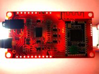
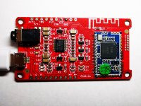
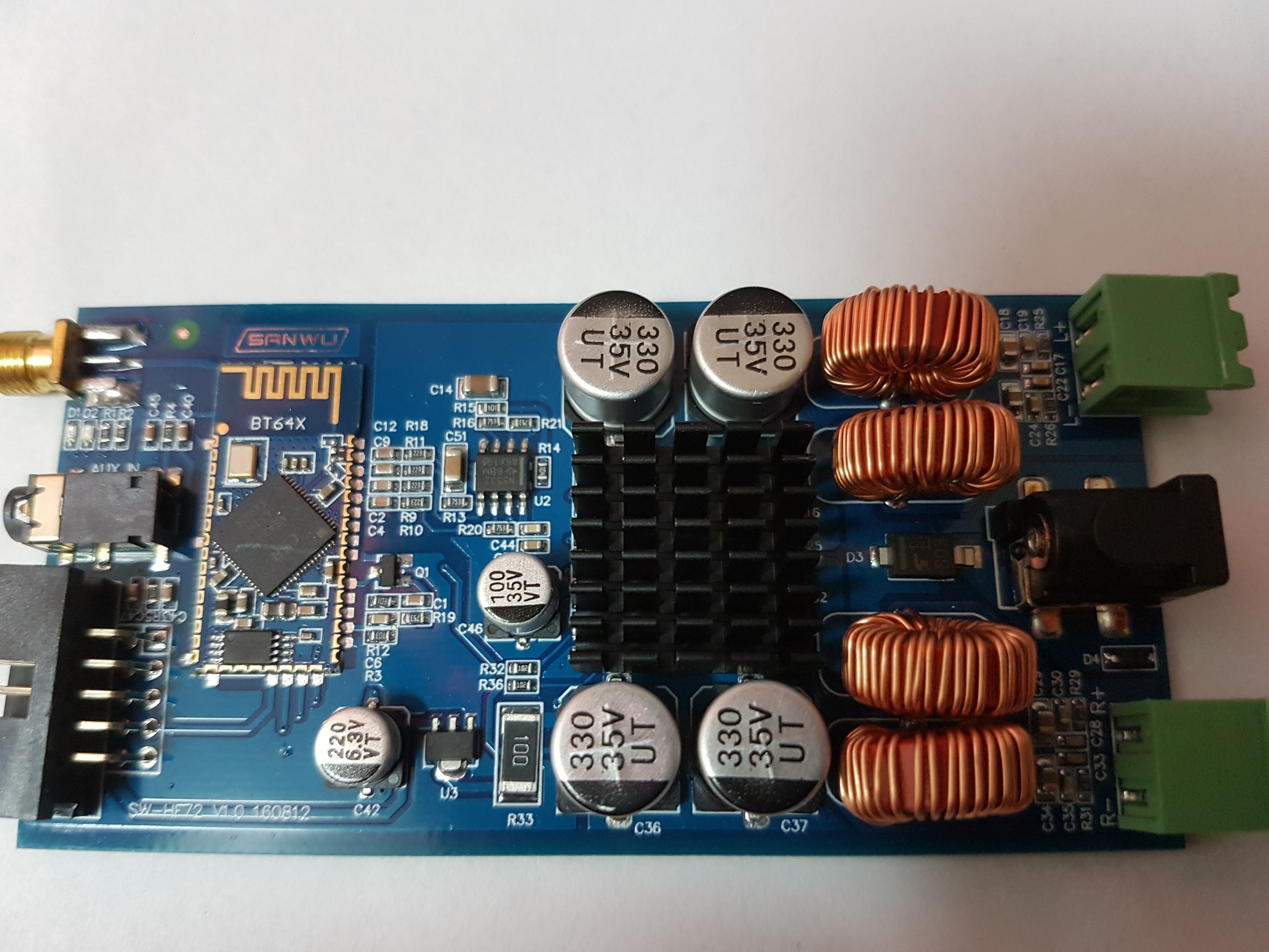
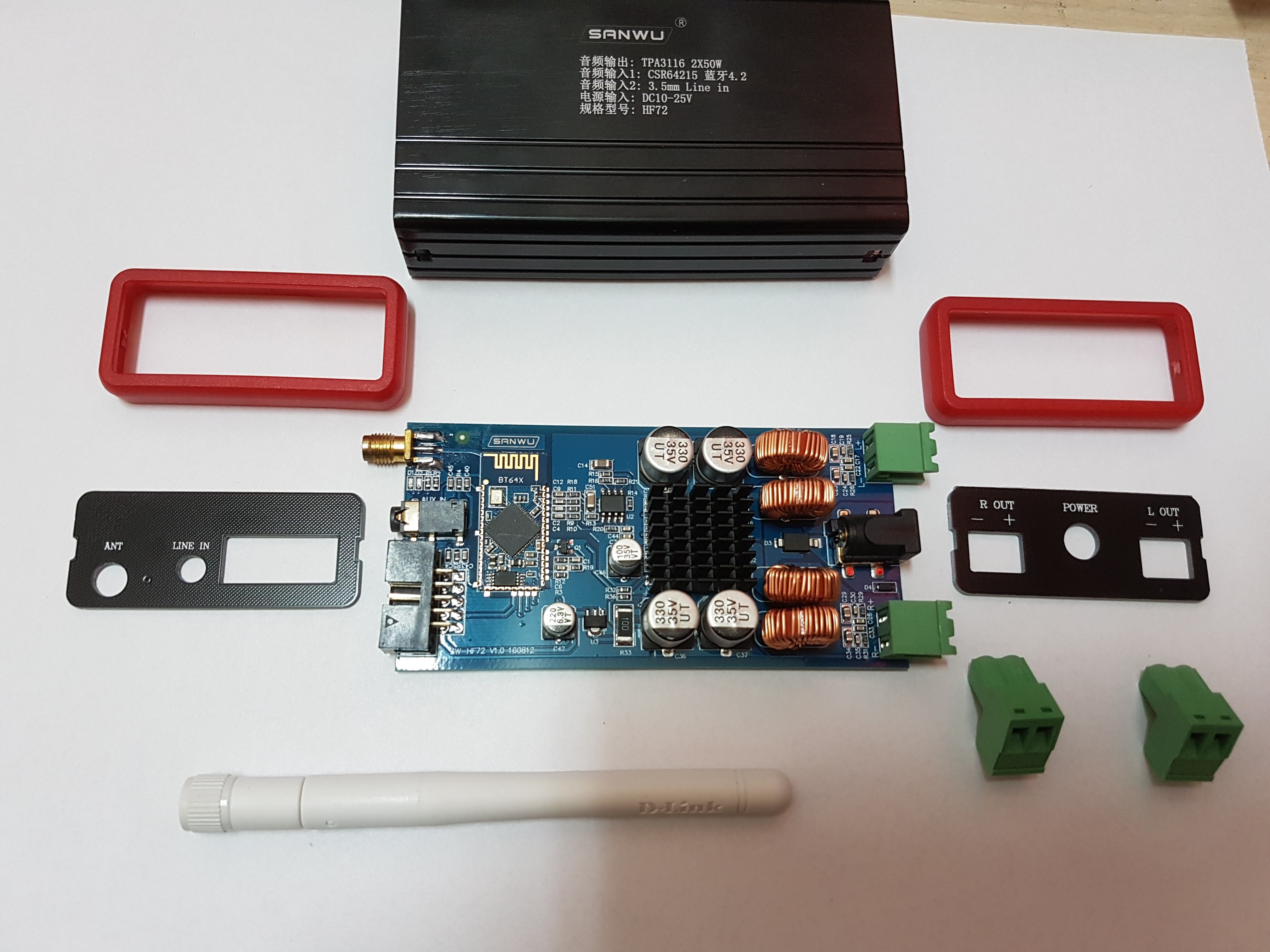
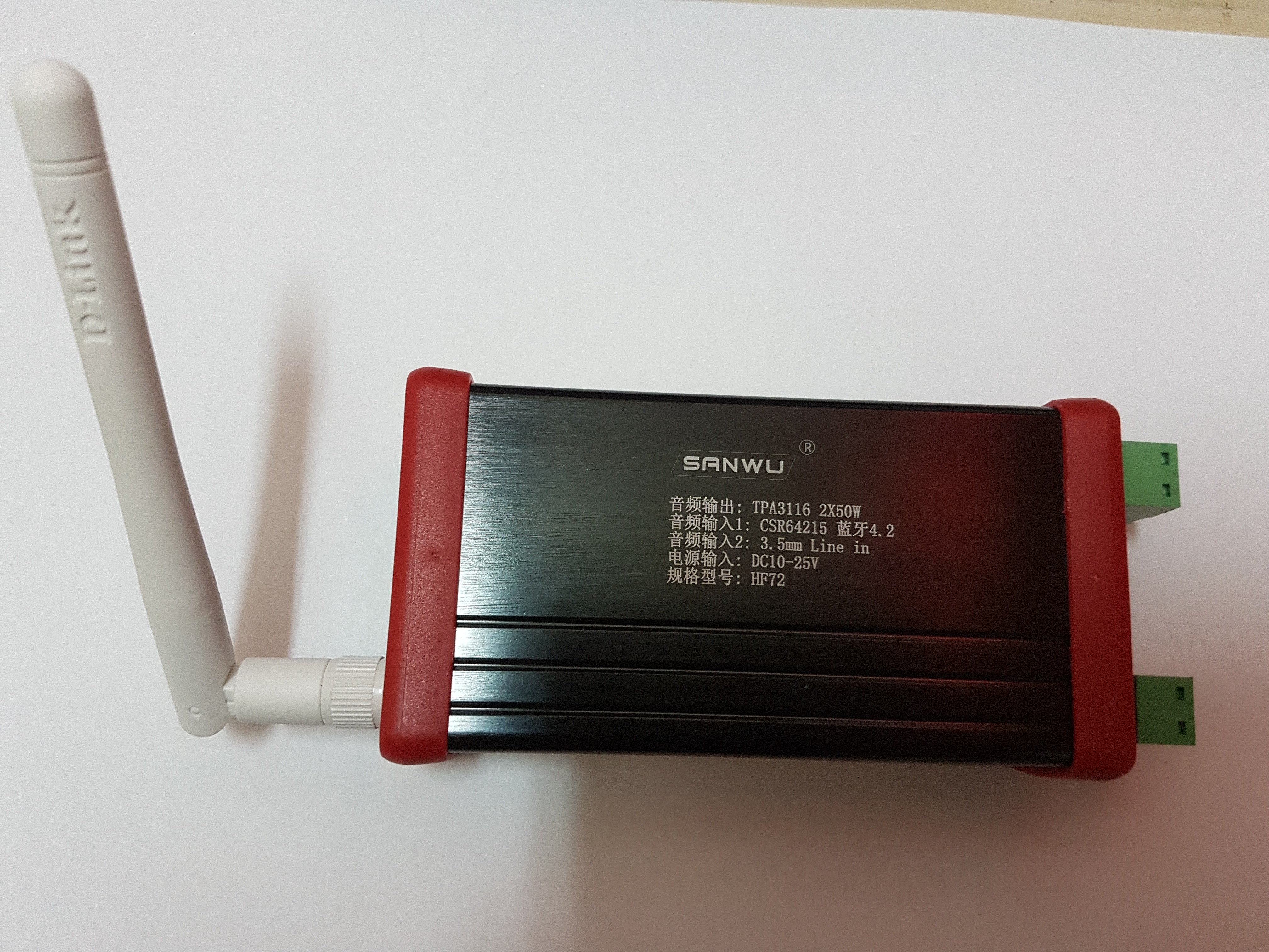
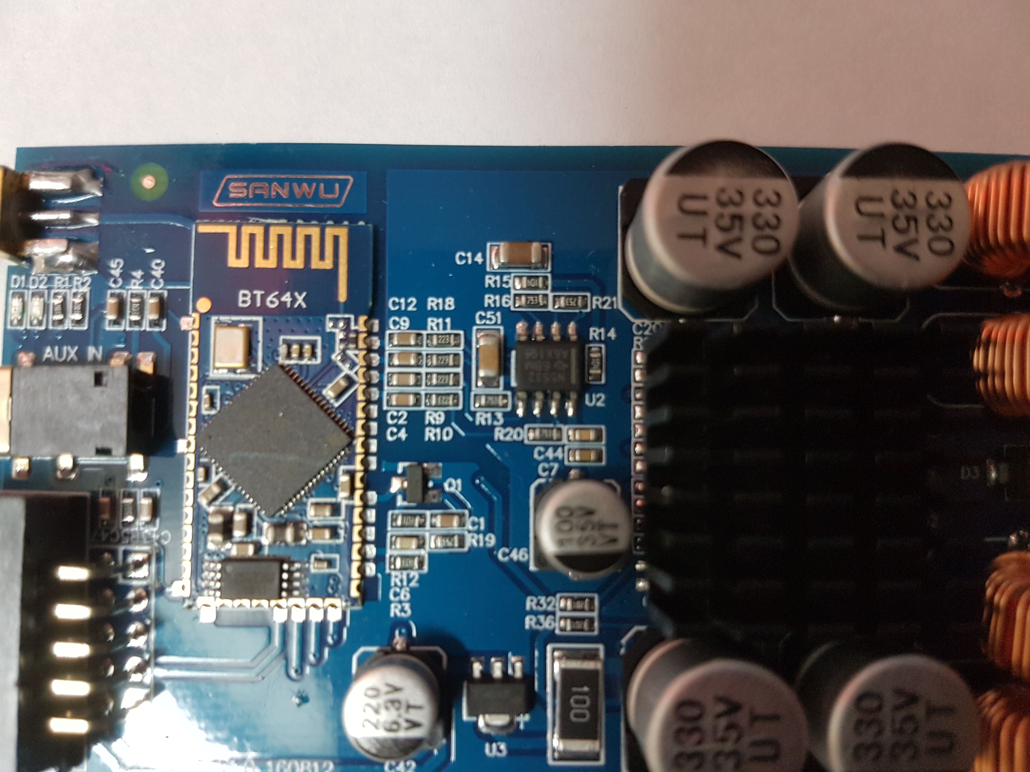
after 5 weeks of waiting I finally received this. the BT 4.2 aptx low latency version : SANWU(R) 50W+50W TPA3116 HIFI-Class Wireless Bluetooth 4.2 Amplifier Support APTX Low Delay Sale - Banggood.com
tried it, sounds really good, but also BT hiss... haven't tried the aux in jack yet.
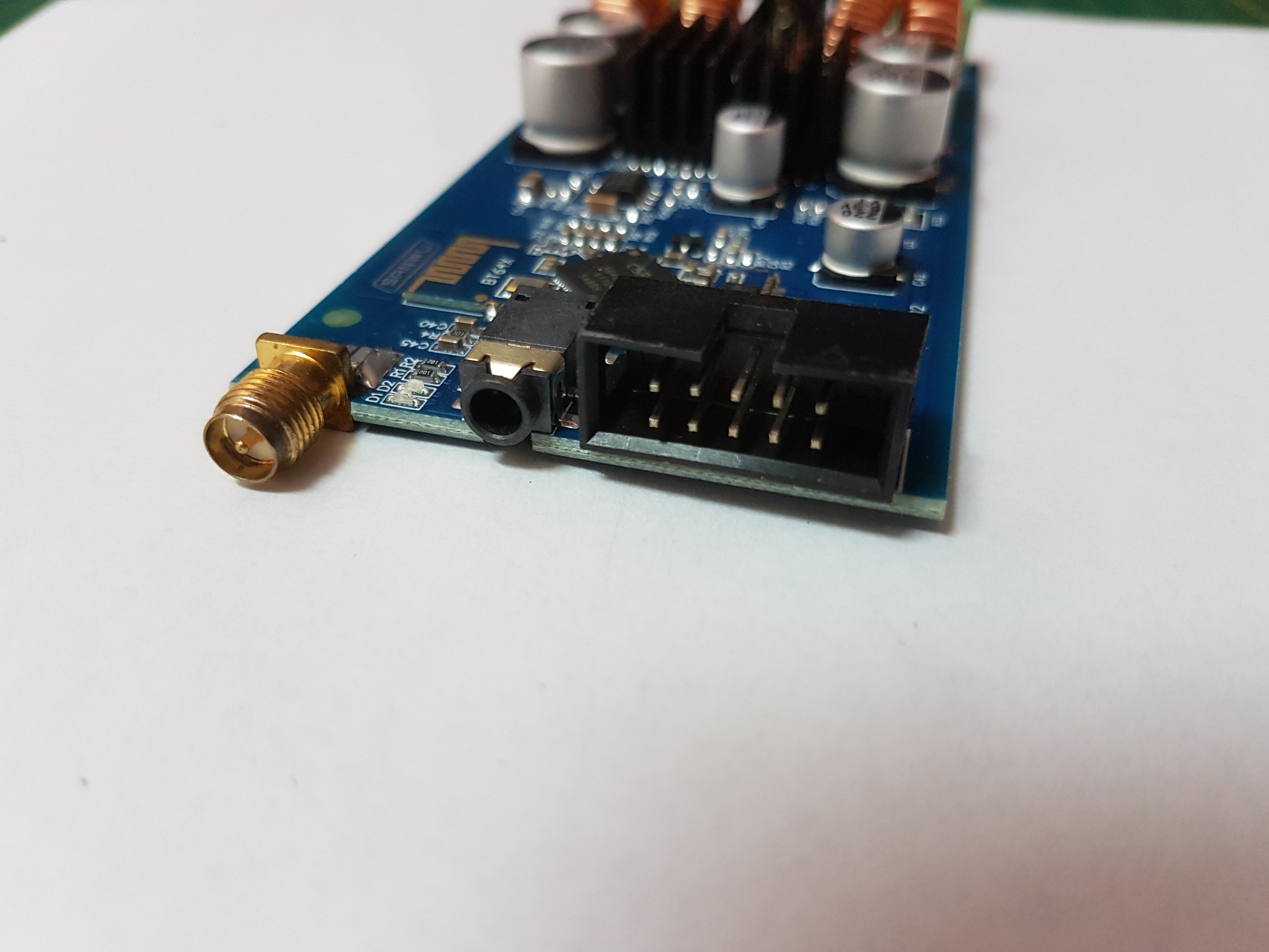
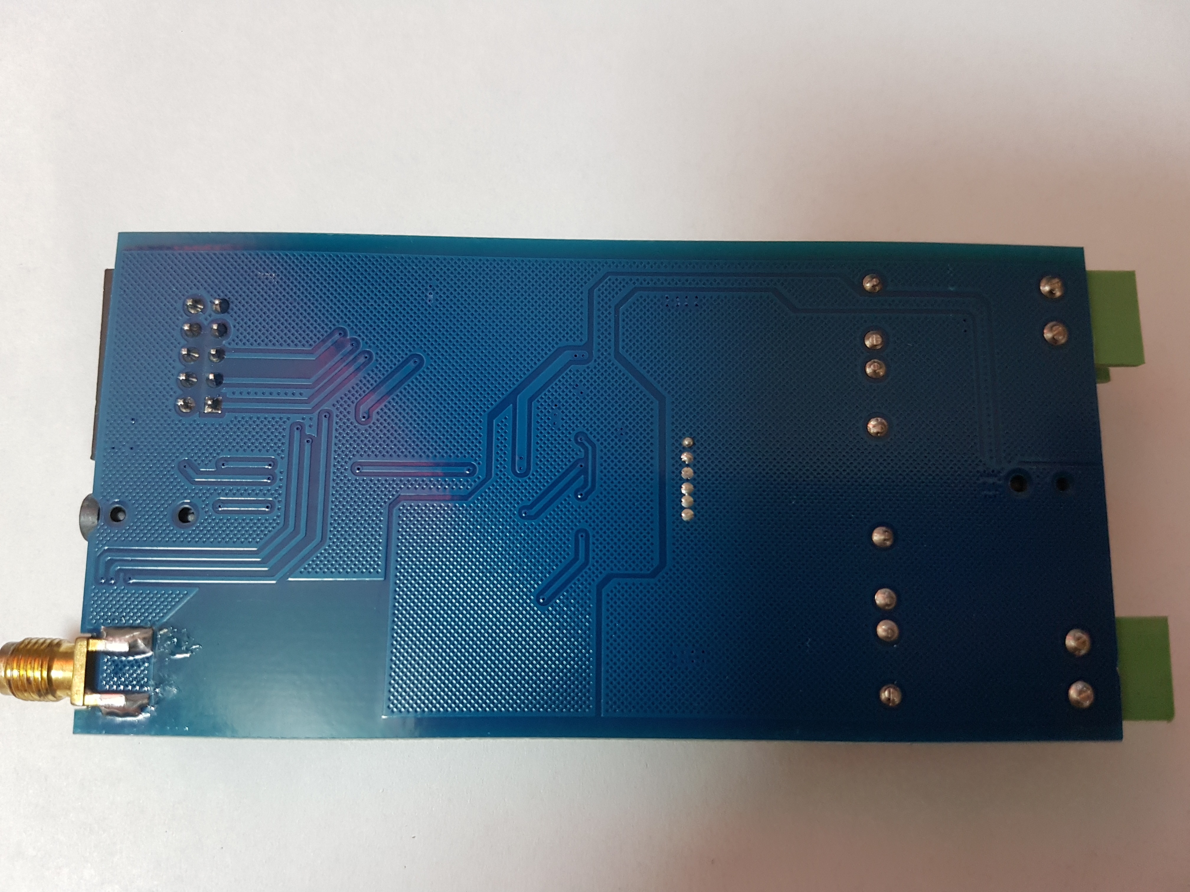
So, before examining the Diff2SE stage I'd post some pictures here:
also todo: figure out the break-out connection on the front, I know already a couple of the pins lead to the bottom of the CSR BT module.
first time poster, long time lurker.
after 5 weeks of waiting I finally received this. the BT 4.2 aptx low latency version : SANWU(R) 50W+50W TPA3116 HIFI-Class Wireless Bluetooth 4.2 Amplifier Support APTX Low Delay Sale - Banggood.com
tried it, sounds really good, but also BT hiss... haven't tried the aux in jack yet.
So, before examining the Diff2SE stage I'd post some pictures here:
also todo: figure out the break-out connection on the front, I know already a couple of the pins lead to the bottom of the CSR BT module.
Hi,
This isn't a question about the sound quality (yet), but with some of the technical knowledge on display some have on here you may be able to help.
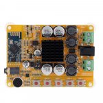
I've bought this board.

I needed the one with the input jack and bluetooth and unfortunately I got the one with bluetooth only.
Rather than get rid of the board I thought I'd try soldering a jack to the pins itself. Would they need to be connected to the TPA3116 chip, pins INNB, INPB, INNA, INPA?
Or would it be the LINE_AN/AP and BN, BP on the bluetooth module?
Would be grateful for some input on this.
This isn't a question about the sound quality (yet), but with some of the technical knowledge on display some have on here you may be able to help.
I've bought this board.
I needed the one with the input jack and bluetooth and unfortunately I got the one with bluetooth only.
Rather than get rid of the board I thought I'd try soldering a jack to the pins itself. Would they need to be connected to the TPA3116 chip, pins INNB, INPB, INNA, INPA?
Or would it be the LINE_AN/AP and BN, BP on the bluetooth module?
Would be grateful for some input on this.
Last edited:
Hey people,
I need your help... I tried everything and I can not get it working.
See attachment for the board, that I have.
It has a CSR8635 on board.
As you can see it has solderpads underneath, which should be SPI_EN, GND, VBAT, MOSI, CLK, CSB and MISO.
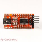
I connected MOSI, CLK, CSB and MISO to my FT232RL module, which I also attached.
I also connected VBAT to 3V3 to FT232RL and 1V8 from CSR to the VCCIO-pin of the FT232RL.
And here is the problem: As far as I know SPI_EN should be pulled high for programming. But as soon as I connect a 10k between SPI_EN and 1V8 (or 3V3), the CSR won't boot anymore... at least the LEDs are not working. Also I can not get BlueSuite to recognize the CSR. Of course I followed all steps from GitHub csr-spi-ftdi.
What do I overlook?!
Thanks!!
I need your help... I tried everything and I can not get it working.
See attachment for the board, that I have.
It has a CSR8635 on board.
As you can see it has solderpads underneath, which should be SPI_EN, GND, VBAT, MOSI, CLK, CSB and MISO.
I connected MOSI, CLK, CSB and MISO to my FT232RL module, which I also attached.
I also connected VBAT to 3V3 to FT232RL and 1V8 from CSR to the VCCIO-pin of the FT232RL.
And here is the problem: As far as I know SPI_EN should be pulled high for programming. But as soon as I connect a 10k between SPI_EN and 1V8 (or 3V3), the CSR won't boot anymore... at least the LEDs are not working. Also I can not get BlueSuite to recognize the CSR. Of course I followed all steps from GitHub csr-spi-ftdi.
What do I overlook?!
Thanks!!
Attachments
hi guys…
quick question about the bluetooth board on these amps…
I've desoldered mine and took it of because I'd like to use the amp just with a line input for my application..
as the bluetooth board has aptx I'd like to use it for a ifferent application..
so, powered connected vbat and gnd and the line outs, but when applying the appropriate voltage (4.2v) it doesn't start up.. (eg. not found thourgh cell Phone bluetooth).. I've not conneted any leds yet.
Anyone knows if I need to connect something different first before the board powers up? (i know I've desoldered more than the 6 leads I've soldered on now, buy mainly pinouts to the connector on the front, see a couple of posts ago)
thanks.
Thank you very much!!!
I did it, and it works! Noise is no more present!
But i have a feeling that speakers are quieter now, volume is lower i think... Is this normal?
I got this Bluetooth amplifier thesame.
When I power on beep on speaker, I connect my Android. Connected, and play some music, after a several seconds no sound but still Bluetooth connection remain and I can control the bottom.
Hi all
Some time ago, orto wrote here:
If I buy an amplifier board that has a BT module in it too,
such as the CSR8635 or CSR8645,
in their spec, those BT modules say "5-band EQ".
How do I access and change it?
Some time ago, orto wrote here:
So far I have only changed the name of the Bluetooth device and used the 5 band eq to apply some baffle step compensation. But there are many many things you can change.
If I buy an amplifier board that has a BT module in it too,
such as the CSR8635 or CSR8645,
in their spec, those BT modules say "5-band EQ".
How do I access and change it?
- Status
- This old topic is closed. If you want to reopen this topic, contact a moderator using the "Report Post" button.
- Home
- Amplifiers
- Class D
- SANWU TPA3116 + CSR8635 Bluetooth 4.0 - Noise Fix