Sorry to bump an old thread, but this is the place to discuss.In addition to this thread:
http://www.diyaudio.com/forums/clas...bluetooth-speaker-protection-eq-any-good.html
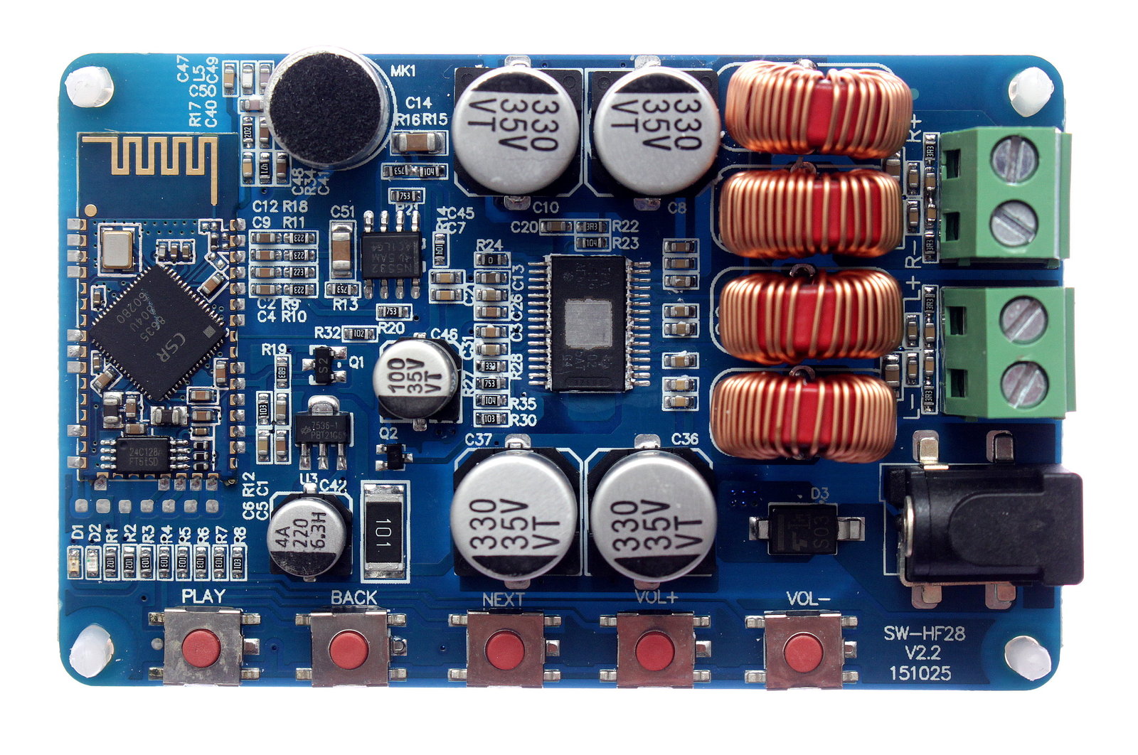
I just bought one of these boards to measure how they'll do and got a v2.2.
Sticking down a heatsink like this is rather useless. Anyway, cleaning the snot off:
Listening to this amp reveals a slight "hiss" of HF/RF interference when having a stream connected and muted or having quiet passages in the music/sound.
From the other thread:
Point 2 is fixed now.
As the noise is independent from the CSR's digital volume level, the hiss is suspected to come from the link between the CSR8635 module and the TPA3116 itself and/or most likely from the power supply design.
Sanwu decided to do a Differential 2 Single-Ended Conversion to feed the TPA3116, why ever, as shown here
Having a direct differential link is all it needs to be dead quiet, so more hiss/noise.
The populated coupling caps are 4.7uF in 0603, most likely X5R 6.3V, so with 32dB gain and 15k input impedance, the f3 frequency will be at 2.3Hz. Changing them for 1uF X7R would give 10.6Hz, still low enough for normal listening.
Another benefit is the now lowered quiescent current.
")
I have the same exact board as pictured in the first post. My application for this board is not necessarily high-res, so I'm not ultra concerned about every tiny hiss. But... that said... it seems the gain is just set too high. There's a touch more hiss at low/no volume than I'd like and the power-on tones are a touch too loud (don't really care for them at all, but I could live with them if they weren't so loud).
I've bought a few of these tiny ~$15 chip amp board with bluetooth built on. Some have dip switches which allow you to adjust the gain. One had a footprint for the dip switches, but zero ohm resistors soldered in place, shorting it, thereby making it set to max gain (33.6db). Simply popping out those resistors opened the trace and thereby set the gain to minimum (21.6db), which made it sound a WHOLE lot better. I'd like to this similar/same to the board shown in the first post. The board seems to make enough power for my application, but the last 1-2 volume steps on my phone lead to heavily distorted music and the power-on tones suck. (I only use bluetooth and only at the default board volume level, I never touch any of the board's buttons). So, simply, how do you adjust gain on this board? I see in the TI datasheet, it listed R1 and R2 values, but where are those on this board? Am I on the right path?
Sorry, I'm a noob.
haha I'm actually planning on building a little boombox for myself and another for a friend, so it's more of a user experience thing. I don't need to hear the "It's pretty good. Distorts if you turn it up all the way, but it's alright" line. Plus like I said, the power-on tones are too loud.Why not just skip the last 1-2 steps on your phone?
Is you mod basically just lowering the noise floor? That would solve the hiss/noise at low/no volumes that I mentioned. I could live with that, but it's a bit more than I'd like. Lowering the gain seems to be the answer to all my complaints. I know on the KKmoon TDA7492P board I have with the zero ohm resistors, the manufacturers had the gain pegged at max. I kinda figured that's what was going on here too.
Are the resistors labeled R1 & R2 on the board the same referenced by TI for gain adjustment? Might seem like a dumb question. But on extremely similar boards, R1 and R2 are not for gain. Or anyone just have a schematic for the board in the OP?Why not just skip the last 1-2 steps on your phone?
Are the resistors labeled R1 & R2 on the board the same referenced by TI for gain adjustment? Might seem like a dumb question. But on extremely similar boards, R1 and R2 are not for gain. Or anyone just have a schematic for the board in the OP?
post #1 got information in photo's, 32dB label.
Gain in part is opamp, so if you removed that opamp...
Ahhh scheisse... you're right. I see it now. The bright yellow lines had my toddler attention.post #1 got information in photo's, 32dB label.
Gain in part is opamp, so if you removed that opamp...
FWIW to anyone reading this, it's R27 and R28 on the board. DoctorMord has them circled in his pictures in the OP and I verified them off pin 8 of the amp before ripping them out. The values I had in those locations measured 75K in R27 and 33K in R28. Though those values aren't listed in the gain section of the TPA3116 datasheet, the "voltage divided" between them points to 32db (~33-34db to be exact). I threw in 100k and 20k (26db setting) 0603 resistors and am a happy camper now. Same speakers, same input device used, same media being played. Now very little/no detectable distortion at max volume. Honestly, I didn't notice a reduction in output either. There's still some hiss with the volume on zero. No biggie. I might try the 20db setting just for the hell of it. Or just go ahead and do Dr's mod.
Side notes, the speakers I used had a dcr of 3.2 ohm and it played just fine.
With 15.5V input into 4 ohm loads at the default ~32db gain, I benched 21WRMSx2 @ 1% THD and 26WRMSx2 @ 10% THD. I also tested at 11.5V and got 12WRMS @ 1% THD and 15WRMS @10% THD.
Signal to noise at 20W was ~76db AU weighted. Again, at the "stock" ~32db gain setting. TI claims 102db at 20db gain setting.
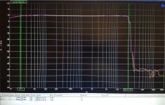
Attached is the power vs THD chart @ 11.5V input. This does improve with more voltage in, but I wanted to test around the voltages I would be using it at. Also attached is the frequency response curve. As you can see, pretty darn flat through 20kHz....which is something I have NOT seen on other similar boards. The yellow TDA7492 board for example.
Now then, maybe somebody could help me with knocking a bit of bass off this? I don't need response down to 20Hz. If I'm reading the datasheet correctly, my new input impedance is 30k ohm with my adjustment to gain. So I should lower the input capacitance? I guess I'd like to shoot for around 40-50Hz with a hard roll-off, maybe even 24db/octave. I can't figure out their little formula there...
Honestly, I didn't notice a reduction in output either. There's still some hiss with the volume on zero. No biggie. I might try the 20db setting just for the hell of it. Or just go ahead and do Dr's mod. Side notes, the speakers I used had a dcr of 3.2 ohm and it played just fine.
With 15.5V input into 4 ohm loads at the default ~32db gain, I benched 21WRMSx2 @ 1% THD and 26WRMSx2 @ 10% THD. I also tested at 11.5V and got 12WRMS @ 1% THD and 15WRMS @10% THD.
Signal to noise at 20W was ~76db AU weighted. Again, at the "stock" ~32db gain setting. TI claims 102db at 20db gain setting.
Attached is the power vs THD chart @ 11.5V input. This does improve with more voltage in, but I wanted to test around the voltages I would be using it at. Also attached is the frequency response curve. As you can see, pretty darn flat through 20kHz....which is something I have NOT seen on other similar boards. The yellow TDA7492 board for example.
Now then, maybe somebody could help me with knocking a bit of bass off this? I don't need response down to 20Hz. If I'm reading the datasheet correctly, my new input impedance is 30k ohm with my adjustment to gain. So I should lower the input capacitance? I guess I'd like to shoot for around 40-50Hz with a hard roll-off, maybe even 24db/octave. I can't figure out their little formula there...
Attachments
Now then, maybe somebody could help me with knocking a bit of bass off this? I don't need response down to 20Hz. If I'm reading the datasheet correctly, my new input impedance is 30k ohm with my adjustment to gain. So I should lower the input capacitance? I guess I'd like to shoot for around 40-50Hz with a hard roll-off, maybe even 24db/octave. I can't figure out their little formula there...
You are correct, 30K input impedance at 26 dB gain. Lowering the input decoupling cap will yield a 1st order LP filter. The formula is:
F3 = 1 / (2 * pi * C * R) where R is the 30K chip impedance and C is the cap.
For example, a 0.15 uf cap will yield a 1st order LP with a corner freq, of ~35 Hz.
A little algebra and you get C = 1 / (2 * pi * R * F). Of course you limited to readily available cap sizes.
Last edited:
YesThanks for the measurements, is this brickwall at 20kHz+ an AP AES17 Filter?
Anybody have any idea which is the coupling cap? Probing around with a meter points to like 5 different ones.You are correct, 30K input impedance at 26 dB gain. Lowering the input decoupling cap will yield a 1st order LP filter. The formula is:
F3 = 1 / (2 * pi * C * R) where R is the 30K chip impedance and C is the cap.
For example, a 0.15 uf cap will yield a 1st order LP with a corner freq, of ~35 Hz.
A little algebra and you get C = 1 / (2 * pi * R * F). Of course you limited to readily available cap sizes.
Anybody have any idea which is the coupling cap? Probing around with a meter points to like 5 different ones.
Marked picture please?
There are a couple of coupling caps, at least 8 i know on these boards.
Tried the doctormord mod but messed up the board. Hate working on SMD!
Took off the resistors and was joining the wires but since they were thin solid core they were a bit stiff and one side was always coming off when trying to solder the other side because the pads are really tiny. After resoldering 2-3 times the pad came off completely so there was nowhere to attach the wire! Tried to work right on the chip leg but I only managed to create a couple of solder bridges that don't come off with the sucker.......I cannot think of any solution now.
Conclusion : These boards have very thin pads and will only take a couple of solderings before they detach. Also use very thin flexible wire.
Wouldn't it be easier to leave the resistors and take out the NE5532 opamp so that the wires have a larger surface/pad to attach to on the resistor itself?
Fair question.Are the dsp EQ settings easily accessible ? I mean can one apply bass boost or for example the 24dB 30Hz high pass inputfilter someone asked here ?
So after looking over page 14 of the datasheet today, I found that C3 on this Sanwu board is the only cap that has continuity with pin 7. And I believe that's the cap I'm looking for to change the frequency response input to the amplifier? I swapped in a 10nF cap, but haven't had a chance to throw it on the AP and run a sweep yet.Marked picture please?
There are a couple of coupling caps, at least 8 i know on these boards.
Attachments

Well if it's not already painfully obvious, I'm not an EE. I work in the audio industry and have a little electronics training (~18 months), but I'm far from an EE. I should have known that a single capacitor cannot serve as the HPF for an entire two channel amplifier. lol I was just going off the small diagram in the TI datasheet and running with it I guess.
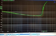
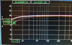
ANYWAY, I found what needs to be done to filter some bass pre-amp. The four caps right out of the bluetooth module need to be dropped in value (see attachment). Which doctor actually hit on in the OP. lol Mine measured ~8.7-9uF. I swapped in 1 uF caps and ran a frequency sweep on the AP (see attached). The top 2 lines are pre-cap change and the bottom two are post-cap change. Keep in mind that I've lowered my gain setting to 26db and thereby input impedance, so my cap values may be different for you with different gain. As it sits, for my needs, I'll probably drop the caps a little lower. That's not much of a HPF.
ANYWAY, I found what needs to be done to filter some bass pre-amp. The four caps right out of the bluetooth module need to be dropped in value (see attachment). Which doctor actually hit on in the OP. lol Mine measured ~8.7-9uF. I swapped in 1 uF caps and ran a frequency sweep on the AP (see attached). The top 2 lines are pre-cap change and the bottom two are post-cap change. Keep in mind that I've lowered my gain setting to 26db and thereby input impedance, so my cap values may be different for you with different gain. As it sits, for my needs, I'll probably drop the caps a little lower. That's not much of a HPF.
Attachments
Are the dsp EQ settings easily accessible ? I mean can one apply bass boost or for example the 24dB 30Hz high pass inputfilter someone asked here ?
If you have a programmer then yes.
- Status
- This old topic is closed. If you want to reopen this topic, contact a moderator using the "Report Post" button.
- Home
- Amplifiers
- Class D
- SANWU TPA3116 + CSR8635 Bluetooth 4.0 - Noise Fix