I was lucky to built one of their (few) Hifi-amplifiers together with the designer ; )
Ik ga toch eens proberen, nu nog bezig met de allfet circlotron met current feedback. en het bouwen van een windings machine voor de input transformer.
vrg kees
Attachments
When you have LC filter outside feedback loop, you also have SPEAKER outside feedback loop !!! Change of speaker impedance (not constant) changes LC filter charactersitics. I would say that maybe real THD can be higher. (maybe, please comment)
Even classic AB class has feedback at the output, at the point of connection of speaker.
This would be great importance of UCD versus sigma delta.
The way to include the feedback it has to be the current feedback type, using the output cap as a means to error correction, for as the class ab version, ik have a hybrid who has not at all feedback, and sounds very very good, such a open way, so feedback is not the best to do, I can make the output coil a air one and use silver mica caps, and use prefeedback to get error correction.
succes
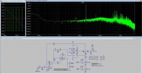
heb de Class D van de universiteit even getekend, en wat gerekend..
I have drawn that class D of the university, so much opamps, I do not now if these will sound well, very high openloop and current + voltage feedback for correction, it do however have no noise trouble, it was in the microvolts without signal while it did switch ahead...
greetz
Attachments
These THD simulations (in general, the ones I've seen in last few pages) are over-optimistic. Distortion from power stage is not being modelled. Distortion of power stage increases for higher operating frequencies (there is an optimum point somewhere in the middle).
In order to get minimum modelling of power stage distortion:
- Add diodes across voltage-controlled switches
- Adjust rise/fall times of switch control signal so that current is switched at about 0.5~1kA/us. Use faster slope for turn off. This can be done with LTSpice parameters for logic gates.
- Add 20~50ns dead time, so that conduction of each switch starts delayed by "dead time" after conduction of the other ends. Again, this can be achieved with LTSpice logic gates, controlled sources, and "delay(...)" function.
Additional note: In practical realization of class D amplifiers, having in the modulator many op-amp stages with high value resistors results in signal integrity problems (unexpectedly high noise, THD, and chances of self-destructive oscillation).
Hi Eva, you are right for shure, mister murphy is here overall present.
The papers who I refer to has much opamps and yes high values of resistors, in there eyes to get low opamp currents, however the modern ones can do better.
Mine simulations has perfetc switches and low pass, as you see even with a very simple amp these hd figures are extreem low for 8 amps output.
the most trouble is because of switch and deadtime trouble, mosfets are because of the capacitances and high voltage switching very difficult to get a very fast transition, maybe with 5 volts but not with 80 volts. Here we can gain much, lime with high current totem poles.
But is is nice stuff to play with, I go make two pcb, one for modulator and one for power stage to experiment after I am done with the analog one.
For the last multi opamp version from a school semitar this is overdone afcourse.
The last pictures I have dead times in the switches and delays, I have also a model with IR2010 who do not model the deadtimes on the right way, I implement but it do not work properly because of the model switching nor the right way or so.
welcome in mine thread.
regards
Attachments

Last edited:
I have change some parts and delay. now it is more in line with reality exept the switches.
did use the ltspice digital parts and now deadtime is much different, capacitor is set t9 470 pF to get rid of shoot trough.. here is the resulting distortion, however the osc frequency is dropped because of more delay, so fase shift network is adjusted.
Still get low distortion, these analog delta sigma do the best of all, but need real time, and I go try, I am curious about these topologies of switching amps.
regards
Attachments
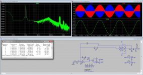
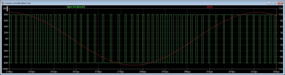
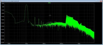
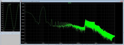
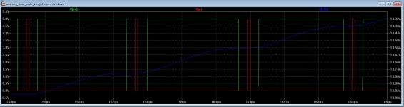
After some thinking I have setup a D amp with capacitor feedback, one who is very simple also, I do not now what I did precisely but I have feed back the capacitor current from the output who is a triangle signal, this do correct for errors very well, even with a extreem large dead time only noise is higher because of lower carrier frequency, did said it looks like current feedback is quite nice.
Last picture you see the error in the switching because of excessive dead time, but HD stay low.
But I like comments about it, maybe I am a gambler in stead of designing.
regards
Last picture you see the error in the switching because of excessive dead time, but HD stay low.
But I like comments about it, maybe I am a gambler in stead of designing.
regards
Attachments
Changing the current feedback resistor in series with output capacitor of low pass give as you see more distortion, most oneven frequencies, see picture one. I did lower it give less feedback, the other feedback line did keep gain the same.
Attachments
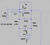
I have this from a paper, a current feedback video opamp I to U can be used for more things like instrumentation amp.
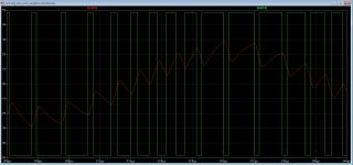
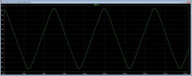
Only I get a square output, and needs to be a triangle.
The current of the output capacitor is measured over it with a extra capacitor, using a resistor has to low voltage sometimes.
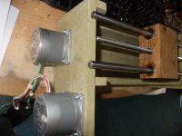
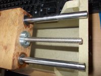
It is done with a current transformer with low leakage, using coax cable as winding.s
regards
Only I get a square output, and needs to be a triangle.
The current of the output capacitor is measured over it with a extra capacitor, using a resistor has to low voltage sometimes.
It is done with a current transformer with low leakage, using coax cable as winding.s
regards
Attachments
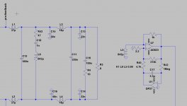
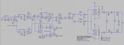
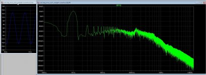
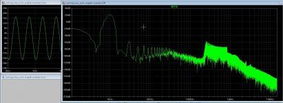
This is the way I did the full bridge, using diff amps in feedback.
carefull with the resistors, maybe paralelling a cap with resistor over the lowpass can can work better.
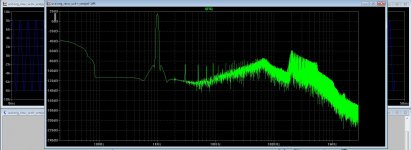
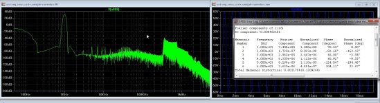
Now I get -80 dB 18 amps peak peak in 8 ohms full bridge, but know I have perfect switches in sims, I need to build if I want to now, so I go build a power comparator separate from the modulator connecting with coax.
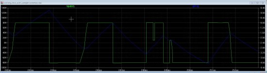
Last two pictures, very high deadtime and the resulting distortion who did rise to -60dB 18 amps output 8 ohm.
regards
carefull with the resistors, maybe paralelling a cap with resistor over the lowpass can can work better.
Now I get -80 dB 18 amps peak peak in 8 ohms full bridge, but know I have perfect switches in sims, I need to build if I want to now, so I go build a power comparator separate from the modulator connecting with coax.
Last two pictures, very high deadtime and the resulting distortion who did rise to -60dB 18 amps output 8 ohm.
regards
Attachments

Last edited:
These THD simulations (in general, the ones I've seen in last few pages) are over-optimistic. Distortion from power stage is not being modelled. Distortion of power stage increases for higher operating frequencies (there is an optimum point somewhere in the middle).
In order to get minimum modelling of power stage distortion:
- Add diodes across voltage-controlled switches
- Adjust rise/fall times of switch control signal so that current is switched at about 0.5~1kA/us. Use faster slope for turn off. This can be done with LTSpice parameters for logic gates.
- Add 20~50ns dead time, so that conduction of each switch starts delayed by "dead time" after conduction of the other ends. Again, this can be achieved with LTSpice logic gates, controlled sources, and "delay(...)" function.
Additional note: In practical realization of class D amplifiers, having in the modulator many op-amp stages with high value resistors results in signal integrity problems (unexpectedly high noise, THD, and chances of self-destructive oscillation).
Model kees52 is using has exacly that (which I made) diodes, dead time, THD caused by switch can be increased by increasing dead time. Also delay time is variable
Last edited:
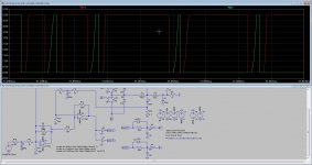
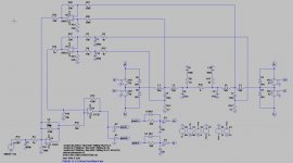
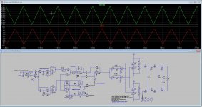
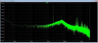
When with the cuurent feedback version using a input triangle, it has also a nice output triangle, the current feedback however is because of difficulty when measure it give problems in the low frequentie band and when low volume, loosing track, so a double feebdack path is used, one current and one frequency feedback.
@Grizlek I have even use 1.5 nanofarad in the dead time, and the current feedback did good work keeping things like hd quite low.
It does work very nicely however need much more work to do before I get something, the version with so much opamps, I put here the .asc, I like people to play with it.
Last two pictures are with high and low deadtimes.
regards
Attachments
Last edited:
Distortion might also increase when increasing supply voltage.
Total distortion in simulation is not important, by increasing dead time it can be even higher then in real circuit. What is important is how different feedback affect distortion in the same kind of main line circuit.
http://www.diyaudio.com/forums/attachments/class-d/658988d1517058486-amp-sound-screenhunter_748-jan-26-22-52-jpg
I meant spice file of this schematics, because some of values are unreadable from image..
I wonder, if you are closes to higher frequencies near 20 khz, is LC filter under high enough feedback not to be seen at transfer amplitude vs frequency characteristics
Last edited:
- Home
- Amplifiers
- Class D
- What Class-D amp give best sound?