I have to try it, I do soon, now I am busy with work. I do not now if with simulation the square test will work properly, I do have to look at output.
I had also try a model from @analogman however with a dead time generator with xor ports I still get shoot throughs, for what concerns the high end distortion, these people has such demands, otherwise you can not sell it to them, if you hear it or not. Class d is less simple as we think, the deadtimes needs to be very tight, and as such we need a very fast transitions or speed, I did try a emittor followed totem driver and a single totem driver, the first did very well driving big mosfets with high gate capacitances..
Adding more poles do not go without trouble, there is a border for how far you can go, but it do work very nicely, I do also use a fase network on the output and a 12 dB octave bessel low pass..
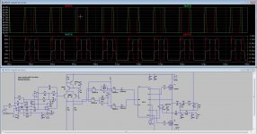
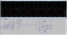
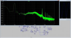
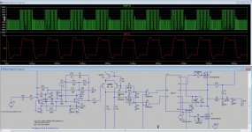
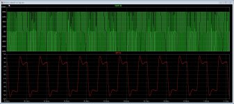
I did try a deadtime on this schematic, however it do not cancel out the shoot through, I think the IR2011 model is not oke, also because I get less negative swing as positive and the square do not look oke.
I have now a model of a IRS20954 who has dead time in it, and a single input, that is more easy to use, did hear it is more sensitive for pcb design, but that is with all high speed switch designs.
Last picture is without the dead time and the first with, it looks like things are reversed so the dead time do not work, it even give more shoot through.
Attachments
Last edited:
I have to find schematics that I use.. Completely remove output stage it will be faster simulation.. and instead of fets use voltage controlled voltage sources, dead time can be generated using RCD circuit (any dead time you want), and delay can be manually added by transmission line. (any delay you want) ... Remember me to post in next days...
Dead time will not prevent shout through and instability.. dead time is 50- 100 nS.. instability lasts at least 2-3 periods of pwm signal..
Like I said "Russian metthod" they probably copied original hypex from Bruno is better (but havent tried it) ...
Dead time will not prevent shout through and instability.. dead time is 50- 100 nS.. instability lasts at least 2-3 periods of pwm signal..
Like I said "Russian metthod" they probably copied original hypex from Bruno is better (but havent tried it) ...
days...
Dead time will not prevent shout through and instability.. dead time is 50- 100 nS.. instability lasts at least 2-3 periods of pwm signal..
Like I said "Russian metthod" they probably copied original hypex from Bruno is better (but havent tried it) ...[/QUOTE]
You did give me an idea.
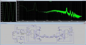
I have done the discrete comparator, this was from internet and with dead time I get this, and low distortion. The choise of the opamp integrator is very important, speed is needed for a clean output square.
regards
Dead time will not prevent shout through and instability.. dead time is 50- 100 nS.. instability lasts at least 2-3 periods of pwm signal..
Like I said "Russian metthod" they probably copied original hypex from Bruno is better (but havent tried it) ...[/QUOTE]
You did give me an idea.
I have done the discrete comparator, this was from internet and with dead time I get this, and low distortion. The choise of the opamp integrator is very important, speed is needed for a clean output square.
regards
Attachments

You did give me an idea.
I have done the discrete comparator, this was from internet and with dead time I get this, and low distortion. The choise of the opamp integrator is very important, speed is needed for a clean output square.
regards[/QUOTE]
Forum member Sous (dont know if russian or indonesian) there was a link to russian forums. huh..
all in all feedback is advanced integrator with special circuit for preventing selfoscillation and instability.
This method full differential UcD modulator with extra integrator
Use single (non differentical) at the begining.. Try to simulate, you will get very low thd, but it will be very unstable if modulation is 60V peak and supply is 80 V peak.. only low pwm modulations are stable. Special circuits that shorts some pole/zeroes of integrator are needed. The same method uses Bruno Putzeys and hypex.
Maybe Sous schematics and design is free ?! But there was link to russian forums there full schematics give.. try to find and post here if you can (I had no luck)
Here you can see how transistor network shorts additioanl poles/zeroes of integrator. Have not tried with this in spice. This method is better and more stable then you posted. thd is below 0,001 (all powers) etc..
http://www.diyaudio.com/forums/atta...cd-modulator-extra-integrator-fd_mdr-4_09-gif
here is it
Automotive UcD high-quality power amplifier 2x100W
????????????? ????????????????? ?????????????????? ?????? ????????? 2?100?? - ???????? 3
Viewer for layout and schematics lay files in zip folder
KOSTENLOSE DATEI-VIEWER, ELECTRONIC-SOFTWARE-SHOP
Last edited:
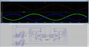
I did this one also, but is from somewhone else, it is like with normal amps, the ideas are look alike, the combination is what matters.
I am a analog amp designer, combiner, class D not yet done really, but it is nice to play.
I had a idea also to do a open loop version full bridge, but I did see that it is not easy, likely very unstable also, I do not now that a ucd with feedback before the low pass can be considered open loop? I think I can not compare the feedback loops with analog amps where feedback do inpack audio depth, that is why I do use current feedback there, independent of bandwidth is a very good thing, special for imd, Designers going digital to try to do no feedback slowly get furter to working one, the designs who work do not sound wel yet as I did read on internet.
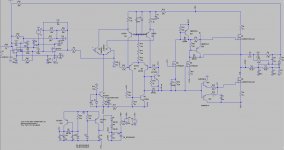
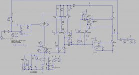
Last picture is a discrete power comparator with under 100nS speed with the right parts, special the output mosfets, a same one I did replace the upper and lower driver for a emmittor followed totem pole, it makes even nicer square on higher frequency, see the low pass filter who has multiply poles and a fase correction network on output I had this idea from the internet, it is not complete mine idea, as I say earlyer everything is alrweady tested by university people or designers from big electronic companys, switching amps was already present in 1950.
As what I do now now, speed is mandory for a low distortion, the poles needed for stability, or even to much works against us afcouse, it is a modulated carrier so as with FM radio it needs much attention for liniarity.
I am a analog amp designer, combiner, class D not yet done really, but it is nice to play.
I had a idea also to do a open loop version full bridge, but I did see that it is not easy, likely very unstable also, I do not now that a ucd with feedback before the low pass can be considered open loop? I think I can not compare the feedback loops with analog amps where feedback do inpack audio depth, that is why I do use current feedback there, independent of bandwidth is a very good thing, special for imd, Designers going digital to try to do no feedback slowly get furter to working one, the designs who work do not sound wel yet as I did read on internet.
Last picture is a discrete power comparator with under 100nS speed with the right parts, special the output mosfets, a same one I did replace the upper and lower driver for a emmittor followed totem pole, it makes even nicer square on higher frequency, see the low pass filter who has multiply poles and a fase correction network on output I had this idea from the internet, it is not complete mine idea, as I say earlyer everything is alrweady tested by university people or designers from big electronic companys, switching amps was already present in 1950.
As what I do now now, speed is mandory for a low distortion, the poles needed for stability, or even to much works against us afcouse, it is a modulated carrier so as with FM radio it needs much attention for liniarity.
Attachments
-
 ScreenHunter_539 Dec. 08 00.30.jpg74.6 KB · Views: 86
 -
 ScreenHunter_536 Dec. 07 16.42.jpg257.3 KB · Views: 86
 -
 ScreenHunter_528 Dec. 01 22.56.jpg289.3 KB · Views: 79
 -
 ScreenHunter_540 Dec. 08 00.31.jpg299.3 KB · Views: 93
 -
 ScreenHunter_538 Dec. 07 22.27.jpg283.5 KB · Views: 1,024
 -
 ScreenHunter_537 Dec. 07 16.43.jpg158.1 KB · Views: 117
Last edited:
I did this one also, but is from somewhone else, it is like with normal amps, the ideas are look alike, the combination is what matters.
But is not this approach better then this method you used in the first place (with LC filter phase correction) which is not stable ?
This method presented Sous seems much simpler, achieves better thd and even more stable..
But you did not try to incorporate "transistor network" which is used for stability, see below ?
http://www.diyaudio.com/forums/atta...cd-modulator-extra-integrator-fd_mdr-4_09-gif
Last edited:
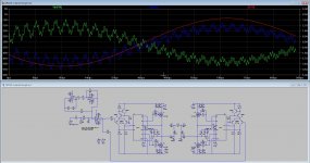
The fun afcouse to do it myselfs, otherwise I have no fun, so combine the things.
The fase correction version looks stable, when bridge these it does give a nise stable output where the voltages are correct. see picture
For me it is just learning and testing, not yet plans to build, I do work on the analog amp and build a winder, but not yet all parts, so did test here some D things.
I admit, the D is quite a interesting technology.
Attachments
I can not really help you <snip>
+1 for Sure AA-AB32313 (MkII) + Meanwell.
^ I probably know why he didn't like the 48V supply.
I played with the supply voltage.
It sounds nice smooth and relaxed at 36 V.
When I increase the supply voltage to 40 V it begins to sound a little more harsh/bright.
Still very very good but not that smooth like at 36 V.
I played with the supply voltage.
It sounds nice smooth and relaxed at 36 V.
When I increase the supply voltage to 40 V it begins to sound a little more harsh/bright.
Still very very good but not that smooth like at 36 V.
But is not this approach better then this method you used in the first place (with LC filter phase correction) which is not stable ?
This method presented Sous seems much simpler, achieves better thd and even more stable..
But you did not try to incorporate "transistor network" which is used for stability, see below ?
http://www.diyaudio.com/forums/atta...cd-modulator-extra-integrator-fd_mdr-4_09-gif
The way I did was feed forward with the network, it do work, however when have to much poles things get worse, afcouse I need to build it to now it, so I ordered parts, the speed of mosfets and speciial comparators and opamps is very important to get low hd, I am busy with a open loop full bridge, try to get distortion low, here I can not implement poles, and a current feedback one.
Then I have enough things to do, also the analog amp and winder.
The fun afcouse to do it myselfs, otherwise I have no fun, so combine the things.
The fase correction version looks stable, when bridge these it does give a nise stable output where the voltages are correct. see picture
For me it is just learning and testing, not yet plans to build, I do work on the analog amp and build a winder, but not yet all parts, so did test here some D things.
I admit, the D is quite a interesting technology.
Can you try this?! instead sine put square signal at the input and see if output is stable ?
Let the output voltage peak be at least 80 % of Vcc...
For what I have to test? I presume the fase correction type, who is in fact feed forward technology I have read on year ago, old and never implemented maybe just the reasons you mention.Can you try this?! instead sine put square signal at the input and see if output is stable ?
Let the output voltage peak be at least 80 % of Vcc...
I test also with a transistor hysteresis on output so the stability get much better also did read somewhere. What you mentioned earlier I did read about, that the HD correction schemes introduce instability, yes like mister Murphy
"Anything that can go wrong, will go wrong"
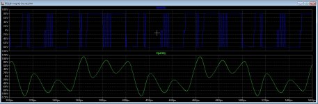
I have sim a btl amp, why I get such strange voltages from output staying negative, while the current waveform is oke. see picture, compare to fase version ucd who is oke.
Attachments

Last edited:
I get even more shoot through with dead time parts, the signals on gates are strange, special the lower one, see the pictures.
I think the IR2011 model is not well.
I somewhone has a better one let me now, this way I can NOT sim right, the maker of the model @analogman can maybe help, because possible I do something wrong.
I can use also IR2110 or IR2092 but have no models, IR2092 is also better with just one pwm input, I have some models but do not work at all.
Thanks in advance
Attachments
Ohh yes I have tryed a square into a amp, this do not go well with fase correction network or lag leg, this I did because it did oscillate on 1 Mhz, that is to high, so grizlek poles are something to be care of.
regards
regards
Attachments
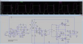
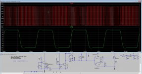
The discrete powercomparator do much more nice then the IR2010 model, I need first good model to test better, so I go with ith discrete one, I presume the IR2110 is also oke, I have 20 of them.
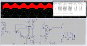
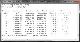
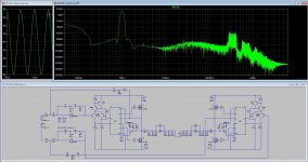
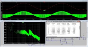
here on high power the distortion, I have dead time so shoot through is limited, this is a ucd version with extra poles but no lead lag or extensive poles who do make unstable, as I did read in the papers, it works but needs precise adjust, HD is very ver low, but this here is more then enough.
Last pic is a square wave signal full power 10 Khz, it looks very stable. If someone has gooed working models for IR2110 or 2092 or IR2010 let me now, there are not much of them.
Ohgh for the one interesed, I get better signal with a bessel lowpass, but then need 12 dB.
regards.
Attachments
Last edited:
Ohh yes I have tryed a square into a amp, this do not go well with fase correction network or lag leg, this I did because it did oscillate on 1 Mhz, that is to high, so grizlek poles are something to be care of.
regards
You will hardly get stable at lower oscillation frequency hmm..
Reduce the square input frequency to about 500 Hz, then zoom PWM more..
I dont bother with driver.. In real design I use IRS20957
Last image looks very stable, whats PWM frequency ? But last image is not POST filer feedback.. it seems to be sigma delta ?!! I would like to see stabiliy for post filter feedback design you have.. (based on Oersted universty paper)
All input and output filter shall be removed to test stability.. when you add filter you reduce bandwidth of amplifier.... and mess up the phase in audio range !!.. For example 50 khz bandwidth audio amplifier has no phase shift in audio range.. Original UCD (the most simple) from patent is like that.. no input filter needed for stability , nor complicated output filter... hmm
I have to post the most simple testing sheme: I dont use any IC nor mosfets.. I use voltage controlled voltage sources and I manually set up dead time and delay..
In real life, you make IRS20957 output section and see whats total delay from datasheets + whats the dead time.. Spice model I use only to test feedback loop. This way time analysis is much faster for simulation
See attachemt, Td I enter manually, and RCD circuit by RC constant I change deadtime.
Attachments
Last edited:
Hi Grizlek
Unfortanely I am not so good with software, so making a own system like you did is out of the question, not a problem because I have time to spent and the simulation goes quite quick with mine pc, big processor.
Is the IRS20957 a good one? I have seen come by mucho of them, not all very good.
Your setup is ideal setup, that is also why I sim with parts models. not always filters are for stability, also the poles of them is used for lowering HD distortion like that I did with the lead lag. I use bessel low pass and do not like overall feedback, that is why I did it that way, a openloop version I did also some time ago, with altering a local feedback the distortions drop mucho without feedback, you need very fast comparators, this is together with width bandwidth opamp integrators..
I go try on and post.
thanks for tips and advise.
- Home
- Amplifiers
- Class D
- What Class-D amp give best sound?