Dammit, anybody change these resistors without the full “smd” setup? I think after the kids catch the bus and they are Definitely not here 🙄 i want to try this.
The cone excursion on my little 3” mid-bass drivers is unsettling. Anybody know why the amp and caps heat noticeably when voltage is higher then 12v? It seams wastefull for a d-class. An AB wouldnt have all the complications of mystery plop/pop (and loud beeping?) with about the same losses to thermal inefficiencies.
I could be off (about the heat) but my tda7498 doesn’t get this hot, not even when i turn it to “11” (that’s a Spinal Tap reference for all you youngsters)
I bypassed that op amp and it really reduced the static noise. It used to be so bad I was going to throw this thing out. Now there is a little but it is acceptably quiet enough that i will not notice it unless I am listening for it. For what I am using this for, it is plenty good enough.
If we bypass the little op amp, is it a good idea to completely remove the op amp? Will it have better battery life without it in a battery powered setup?
If we bypass the little op amp, is it a good idea to completely remove the op amp? Will it have better battery life without it in a battery powered setup?
A smart DC protection circuit will fix the problem.
Mine has a 4 second power up delay.
Then if it sees DC for more than 500mS it disconnects the speaker using a relay.
I use one on the output of an amp test rig and it has saved a fortune in speakers.
Speaker DC protection protector pcb module. | eBay
Mine has a 4 second power up delay.
Then if it sees DC for more than 500mS it disconnects the speaker using a relay.
I use one on the output of an amp test rig and it has saved a fortune in speakers.
Speaker DC protection protector pcb module. | eBay
Hi everyone, Parts Express had a sale on some mini amps that utilized the 7492P and they were only $8.50 including an AC adapter and the amp in a very nice aluminum enclosure. As others are reporting, the ones I got have a really strong thump\crackle from the speakers when I power it on. It did it the first time when the device is switched on and every time after, no matter how long I waited, so it doesn't seem to be a case of caps still being charged when powered on and off repeatedly. I bought two of these and both of them do it. I tried both of the included AC adapters, as well as one I had around.
The board is a bit different (even cheaper) than the one in the OP, but is there any way to mod this thing to get rid of that thump? I intended to use some mini speakers I had from one of those surprisingly decent sounding JVC mini stereos from the 90s, but the turn on thump from this amp makes the speakers visibly pop out, which I don't think they were intended to do!
I took a ton of pictures of the board and saved them to this gallery:
FX Audio 7492P Mini Amp - Google Photos
It appears to be the same as this board:
Yeeco Amplifier Board,TDA7492P 25W+25W Dual Channel Stereo Audio Power Amp Speaker Module,DC 12V-24V High-Power Digital Power Amplifier Board for DIY: Amazon.co.uk: Lighting
Some things I noticed regarding the boards in my amps:
Fake Nichicon 470uf 25v caps (they have + vents, which I don't think I've ever seen on a real Nichicon) - I have quality replacements for these on hand, is it worth doing this? It'd be quite easy but I don't know if it would even make a difference.
Soldering overall looks okay, not a fire hazard as far as I can tell.
Strange ground wire thing going from one of the pins on the volume pot. I think it is there to reduce humming when you touch the knob because I notice a humming when I touch the pot with the pulled away. Seems odd that it is just loosely wrapped and then pinched against the face plate. I doubt I could solder this to the pot without melting anything. Is there some way to improve this? It just seems like a bad connection and a possible source of noise in the future.
Other than the popping, the cheap fake caps and that funky wire though, it seems like an amazing deal for only $8.50. Any of the parts (amp board, casing or 12V 3A power adapter) would have cost $10 or more separately.
Any help with this would be much appreciated!
Hi everyone, Parts Express had a sale on some mini amps that utilized the 7492P and they were only $8.50 including an AC adapter and the amp in a very nice aluminum enclosure. As others are reporting, the ones I got have a really strong thump\crackle from the speakers when I power it on.
That explains the price... no delay turn on.
Amplifiers need a couple of seconds to get them selves organized when first turned on. Generally this is hidden behind either an output muting circuit or a relay to protect the speakers --and your ears-- from huge transients during that moment of instability.
Truthfully... at less than $10.00 I'd just write this one off to experience.
Is there any way to add a delay or filter to these, or modify the circuit in some way to make this less noticeable? Honestly, the $10 isn't the issue, it's that they're otherwise perfect for what I need, I just don't want them to make a loud thump. They are tiny, look great and sound good with anything I've tried so far. I'll be using the amp for a retro-computer setup, where it will be used for playing old game audio (Yamaha OPL3 FM synthesis and a Roland SC-7 Sound Canvas for General MIDI).
You could probably build/find an external relay that you could hook up to your speakers to provide the delay. But it's going to cost a few bucks, probably more than the amplifier itself.
Another choice is to hook it up, turn it on, then plug in your speakers and just leave the thing on all the time.
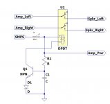
Still another choice would be to use a DPDT switch in the speaker lines and switch the speakers on manually a few seconds after turning on the amp.
Another choice is to hook it up, turn it on, then plug in your speakers and just leave the thing on all the time.
Still another choice would be to use a DPDT switch in the speaker lines and switch the speakers on manually a few seconds after turning on the amp.
Thanks for the ideas, all of those sound feasible.
I have don a fair amount of electronics repairs, but I don't have much experience designing my own modifications for circuits.
I've read a bit about small, solid state relays being good for things like this, but I can't seem to find a discussion that names a specific part (or even some specifications to look for) or how to implement it.
For a relay I would stay with a bog standard coil and contacts device. It would need to be rigged with a simple circuit to delay it's turn on by 4 or 5 seconds when the power supply is turned on.
By putting a jack and plug on the external unit you could also use it to turn the amp on and off.
The attached thumbnail is a quicky drawing to give you a visual... The part values shouldn't be too hard to work out on your own.
By putting a jack and plug on the external unit you could also use it to turn the amp on and off.
The attached thumbnail is a quicky drawing to give you a visual... The part values shouldn't be too hard to work out on your own.
Attachments
Thank you for the schematic, that is very helpful. I guess I should have said I have a fair amount of soldering experience (replacing components) but basically no experience making my own circuits. I wouldn't even know where to start to figure out the values for the components in the schematic. I'm learning slowly by doing projects like this but I'm not quite to where I need to be to read a schematic and fill in the blanks... 
I actually found some relays that I picked up when the local Radio Shack closed. One is a DPDT SANYOU (yes, you!) 5A 250VAC/24VDC | 5A 250VAC relay.
I also have a couple that were harvested from some other devices that say "Delay Line" on them. One is a KSS MS-19, the other is ADL-FN2035C-A02. I'm assuming these aren't some kind of magical devices that contain the delay circuit I need... right?
After looking at the datasheet for the TDA7492P, I see it does actually have a standby+mute startup sequence to eliminate the turn on thump. There are very few components needed for this since the board does seem to have a 3.3v source already. Is it possible that the board just needs some components added or changed out for this to work properly?
https://www.google.com/url?sa=t&rct...tda7492p.pdf&usg=AOvVaw27Ok_vp49JuKaVxHM-9ttb
Just looking at the pictures I took, it looks to me like the STBY and MUTE pins actually connect together with a ceramic cap between them, and then they proceed on (need better pics to see where). Having them connect together doesn't seem to match the suggested schematic in the datasheet. Maybe they are just both connected so that the circuit is "on" immediately.
If it's possible to just add a few components internally I'd really prefer that so I don't have to have an external box.
Sorry for all the posts, I'm not allowed to edit posts.
I just realized the standby+startup thing is just a suggested way to start the amp, not an actual sequence. Meaning, you need buttons for standby and mute. They suggest switching the power on, then switching standby off, then unmuting. How intuitive...
I can either add a tiny toggle switch for mute\standby or if there is a small enough time delay relay board (I see them on eBay) that would fit inside this, I guess that's a possibility, but I don't know enough about these things to know what would work.

Just looking at the pictures I took, it looks to me like the STBY and MUTE pins actually connect together with a ceramic cap between them, and then they proceed on (need better pics to see where). Having them connect together doesn't seem to match the suggested schematic in the datasheet. Maybe they are just both connected so that the circuit is "on" immediately.
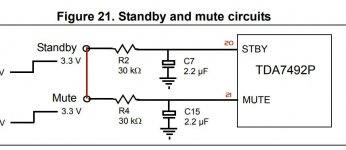
The thumbnail shows the Mute and Standby from the data sheet. I've added the pin numbers and 3.3v connection for you. Now comes the fun part... can you get at this on your board?
According to the data sheet both pins need to be at +3v before the chip will operate... so it's likely they have it tied to 3 volts on the board. So start at pins 20 and 21 and follow that circuit back until you either get the 3 volt rail or (hopefully) a resistor. In practice I would make the cap on the mute circuit a bit bigger than the one on the standby... let it power up before you un-mute it.
If you come to a resistor... that's perfect, all you need to do is change that resistor and add a capacitor to ground, for each pin.
IF you come to the direct rail, you will need to find a point where you can cut the foil, then add the resistors across the cut and caps to ground. This might not be easy as often power traces are buried in layers of the board.
I would say it's doable provided you can isolate those pins from the direct 3 volt rail.
Another consideration might be to troubleshoot those pins with a scope or meter... it's possible the cap(s) you're seeing are either defective or too low in value... in which case a parts replacement might win the day for you.
Attachments
Last edited:
For my dodgy little schematic...
That sounds promising.
The transistor can be almost any NPN power transistor, the good old Tip29 comes to mind and you may already have them in your junk box. At one time they were as common as rice.
Any resistor that will saturate the transistor's base, without destroying it should work fine... Try 56k, 47k, 33k, etc. until connecting the resistor reliably pulls in the relay.
Any capacitor that provides the time delay you want is also just fine... with 47k a 100uf cap would provide a couple of seconds. This too can be determined experimentally. Higher values give longer delays.
If you have little or no experience with this kind of design, this would be a nice, simple, project for you to start with... It's quite the rush when your first actual prototype comes to life and starts working.
I actually found some relays that I picked up when the local Radio Shack closed. One is a DPDT SANYOU (yes, you!) 5A 250VAC/24VDC | 5A 250VAC relay.
That sounds promising.
The transistor can be almost any NPN power transistor, the good old Tip29 comes to mind and you may already have them in your junk box. At one time they were as common as rice.
Any resistor that will saturate the transistor's base, without destroying it should work fine... Try 56k, 47k, 33k, etc. until connecting the resistor reliably pulls in the relay.
Any capacitor that provides the time delay you want is also just fine... with 47k a 100uf cap would provide a couple of seconds. This too can be determined experimentally. Higher values give longer delays.
If you have little or no experience with this kind of design, this would be a nice, simple, project for you to start with... It's quite the rush when your first actual prototype comes to life and starts working.
Okay, I've traced out the circuit a bit more. I was following the wrong pins before (big surprise there). Now that I've identified the right ones, it does almost exactly match the diagram you've shown. I measured 3.3vdc coming from the AMS1117 voltage regulator, going to the shortest leg on the power switch. When switched on (up position) it connects the 3.3v to the middle leg of the power switch, which connects to a resistor for the LED and the 33kohm resistors and ceramic caps (connected to ground) leading to the STBY and Mute pins.
I'm still not sure if I understand this part of the circuit properly, but going by what you said, it seems that replacing those caps with higher values would add a delay and possibly fix the problem? What values would you suggest trying? Also, this may be a dumb question but would I have to use a ceramic SMD cap for this, or would something else suffice? Just for testing purposes, I have tons of other caps, and I down own an LCR meter to be sure of the values.
Also, I noticed something that I couldn't explain when poking around. If I set my Fluke DMM to AC voltage and probe either of the positive speaker terminals with just the red probe, I get a constant 3v to 4v AC even with the power switched "off" (though really, this switch just seems to stop 3.3v from getting to the amp chip... there are still several components that are powered). When I touch the black probe to any ground, or if I touch the casing of the amp it drops the AC voltage to basically nothing.
What is the science behind this and is it normal or a sign of an issue with the design? Both of the amps do this. It seems like it'd be bad to have constant voltage at the speaker terminal with the power off. Like, it'd be audible when connecting the speaker if you connected the positive first, even with the power off.
Thank you again for helping me to understand this stuff. I've been repairing and working on computers for almost 20 years but have only very recently started dabbling in circuits. I've built some speakers (Dayton D8 MTM... biiig ones) but I used other peoples' crossover designs. It'd be nice to understand how everything interacts a bit better some day. Small circuits on PCBs are even more mystifying to me.
Last edited:
Okay, I've traced out the circuit a bit more. I was following the wrong pins before (big surprise there). Now that I've identified the right ones, it does almost exactly match the diagram you've shown. I measured 3.3vdc coming from the AMS1117 voltage regulator, going to the shortest leg on the power switch. When switched on (up position) it connects the 3.3v to the middle leg of the power switch, which connects to a resistor for the LED and the 33kohm resistors and ceramic caps (connected to ground) leading to the STBY and Mute pins.
Okay, so try touching something like 1uf or even 10 uf temporarily across the ceramics and see what the effect is. Be sure to watch the polarity. Do the standby pin first. It should take longer to start up, which is what you want. Once you isolate the right value, you can figure out the best way to do the permanent modification.
Keep in mind that it should come out of mute after exiting standby... so use the next higher standard value on the mute pin. (eg. 1uf on standby, 1.5uf on mute)
I'm still not sure if I understand this part of the circuit properly, but going by what you said, it seems that replacing those caps with higher values would add a delay and possibly fix the problem?
Exactly. The chip has internal logic that switches the outputs off when those pins are low. So when you first turn on the switch the caps are discharged from sitting. They then begin to charge slowly through the series resistor. When they reach the operational threshold (2.5v, if memory serves) the amp comes out of standby and/or mute. The larger the cap the longer the charge time... the longer the startup delay.
What values would you suggest trying? Also, this may be a dumb question but would I have to use a ceramic SMD cap for this, or would something else suffice?
I would start with 1uf and go from there. The higher the value the longer the delay.
Replacing SMD with SMD is always preferable, but a real pain in the patookus. You can tack solder standard through hole parts on there, no problem as long as it's not going to interfere with a heatsink or other parts.
Also, I noticed something that I couldn't explain when poking around. If I set my Fluke DMM to AC voltage and probe either of the positive speaker terminals with just the red probe, I get a constant 3v to 4v AC even with the power switched "off" (though really, this switch just seems to stop 3.3v from getting to the amp chip... there are still several components that are powered). When I touch the black probe to any ground, or if I touch the casing of the amp it drops the AC voltage to basically nothing.
All around us are constant fields of AC. It comes from the wiring in the walls, from nearby transmitters, from devices nearby. It was probably reading your hand which is acting like an antenna. Readings with no ground connection allow the meter to wander and simply cannot be trusted.
Thank you again for helping me to understand this stuff. I've been repairing and working on computers for almost 20 years but have only very recently started dabbling in circuits.
You're welcome... see my signature for a link to one of the best electronics theory sites I know of. It's a very interesting and challenging field of study.
- Status
- This old topic is closed. If you want to reopen this topic, contact a moderator using the "Report Post" button.
- Home
- Amplifiers
- Class D
- How to prevent popping sound on power on on TDA7492P Amp?