Hmm, I overlooked this fact in my quest to reduce components, datasheet snippet made it sound like gain was set automatically internally, but reading it again it does say stage 1 gain is set externally. I suppose then really I should replace that 10kR with a 47kR to bring gain down to a more modest 13dB, or factor 4.5, still into clipping region, but not so bad. Maybe even 68kR to bring gain down to 10dB. That means I can reduce my C value for the filter significantly as well, which should reduce the slight on/off pop that exists.
I might measure my source out of curiosity (that Amazon bluetooth module I took a picture of in the 3118 thread).
I might measure my source out of curiosity (that Amazon bluetooth module I took a picture of in the 3118 thread).
Last edited:
As far as I remember, I had to change the input resistors on my $0.50 PAM boards as well to 47k to get the gain down. 10k is "asian standard". This also brought "noise" down.
I use them without permanent supply but with 2x 25F supercaps in series, so having 12.5F with an ESR of ~70mR at 5V.
I use them without permanent supply but with 2x 25F supercaps in series, so having 12.5F with an ESR of ~70mR at 5V.
Supercaps eh? I happen to have a few of these left over from another project (GS203F)
https://www.tecategroup.com/products/datasheets/cap-xx/CAP-XX GS103 GS203 Datasheet v4-1.pdf
Maybe I will stick one of them in the enclosure to help fill in for any shortcomings of standard USB supplies.
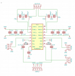
Didn't get a board layout done today, but I did manage to remake the schematic in KiCAD. I am getting there, slowly.
https://www.tecategroup.com/products/datasheets/cap-xx/CAP-XX GS103 GS203 Datasheet v4-1.pdf
Maybe I will stick one of them in the enclosure to help fill in for any shortcomings of standard USB supplies.
Didn't get a board layout done today, but I did manage to remake the schematic in KiCAD. I am getting there, slowly.
Consider using a softstart using a highside switch in front.
Like:
http://i.stack.imgur.com/8PxZ6.png
Transistor base also on the input, capacitor between G-S for softstart time. Or RC at the Base of transistor. Would make also a nice ON/OFF switch.
Like:
http://i.stack.imgur.com/8PxZ6.png
Transistor base also on the input, capacitor between G-S for softstart time. Or RC at the Base of transistor. Would make also a nice ON/OFF switch.
Last edited:
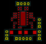
My current plan is to leave it powered all the time and just switch the SHDN pin. Here is the latest schematic and layout. I need to figure out how to do nets in KiCAD so it will let me actually wire it though. It sort of looks like a robot ")
I may do the soft-start as a break-away option. I will definitely include it on my next board which will be higher power though.
I may do the soft-start as a break-away option. I will definitely include it on my next board which will be higher power though.
Attachments
Last edited:
As far as I remember, I had to change the input resistors on my $0.50 PAM boards as well to 47k to get the gain down. 10k is "asian standard"..
I'm a bit clueless about all this, and maybe the 8403 boards I have been using are otherwise different (the ground resistors?), but I was sure the boards I got with 47k input resistors were mistakes. I was actually thinking of trying something a bit less than 10k because it's a bit on the quiet side and I can crank it up with no discernible issues.
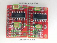
...Otherwise different in that those ground resistors connect to the L/R inputs (black lines)... I don't see this on other 8403 boards (including Jensen's). What is the reasoning/purpose? It would appear that the 47k boards are mistakes. Are the values important? Would it matter if I replaced the 47k w/ 10k or just removed the 10k gnd > L/R resistors?
The other difference between this board and other 8403 boards is the larger caps. Is larger better and what effect does the 10uf VS 47uf have?
Attachments
Hello,
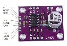
I just received 2 pieces of the CJMCU amplifier based on PAM8406 as in the photo attached, and being a beginner, I have some doubts.
I intend to use for each channel two small speakers, one of 6ohms and the other of 4ohms connected in parallel (approx 2.4ohms). Both are made for up to 5w. I'd like to power the amplifier with 5VDC.
From what I read in the datasheet and testing the card I have, originally the IC is in Class-AB mode since the terminal "DODE" is not connected either the VCC or the GND, but I would like to test the amplifier in the 2 modes: Class -D and Class-AB. From what I understand, to set it to work in Class-D mode I should connect VCC to the "DODE" terminal. Or maybe I should mount a network of resistors between VCC and GND in order to provide some volts less than VCC, maybe 10k for VCC and 18k for GND, resulting in approximately 3.2v for pin 9 of the IC. Am I right?
And after all, the doubts I have are about the differences between these two modes, D and AB. From what I've read I have the impression that the AB mode will make the chip heat up maybe even needing a heatsink, it will not deliver the same power as the D mode to the speakers, which produces greater distortion and noise (THD + N), and still presents quiescent current, which is worse for batteries. That is, I got the impression that Mode D is better in everything, what do you think?
Attachments
I used a PAM8406 to drive Teac LSX-8 speakers for the TV. It is ideal as I was always being told I had the NAD3020 too loud when it seldom hit 5 watts on the power meters. Whilst not sounding the same as the NAD it is a nice replacement. Class D can offer a few class A qualities. Namely voice quality at low volume. I doubt I get 1 watt which isn't a problem. I have run it from a battery pack and TV USB. The latter perfectly OK. This all started to help my son build some active speakers. I liked it enough to want one myself. It is good enough to show the quality of the source. If you study the distortion graphs it's a very good compromise. Sort of like a 1960's amp of good quality. I have used a Hypex amp which was obviously better. Hypex was very fussy about PSU and to my ears not ideal with the Hypex one. There was a metalic quality. The PAM has a hint of that without being a problem. I did notice the battery pack better on that. On the published disortion graphs it looks to be at 5 kHz. A very nice piece of engineering. I suspect the switching is in phase and the music out of phase on the output bridge. If so what a good idea. The distortion graph suggests a wider dead band than better devices. That is a good compromise for safe working.
Checking in on this old thread- did you manage to complete your PAM8406 board? I am looking at this as an option for an active line array. If you completed it I'd be interested in having a few made- I'd need 12 pieces for the array, plus a few extras for me to practice on. Would be happy to compensate you for it.
- Home
- Amplifiers
- Class D
- PAM8406 (and PAM8403)