L chanel: sound card line out=>amplifier =>divider 1/10=>sound card line in
R chanel: sound card line out=>sound card line in (we call it a through channel measurement)
ah that makes sense
Thanks!Very nice job.
just finished testing the first sample
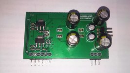
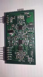
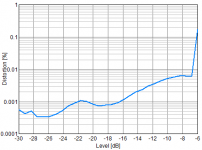
THD on load 3.3 Ohm. PS - 50Hz 120W transformer with 2x30V
winding.
-6dB=130W (135W-amp clipping)
scale in decibels - the input level of the audio card
Attachments
Last edited:
))Thank you Sous, it seems that I need to renew the knowledge of the Russian languageNo, in real earnest it is all clear, I like projects from this forum.
C'est La Vie.
In the first post there inverter circuit are you looking for
Fully Differential UCD Modulator
Hello Sous,
Thanks for sharing the circuit. Is this the one you have implemented in your final version? Kindly help me understand the function of the circuit based around the matched transistors pairs BCV6x.
Thanks in advance!!
slightly modified the concept
based on ncore white paper.
Hello Sous,
Thanks for sharing the circuit. Is this the one you have implemented in your final version? Kindly help me understand the function of the circuit based around the matched transistors pairs BCV6x.
Thanks in advance!!
Fully Differential UCD Modulator
I guess the circuit around DCV6x acts like a limiter. But I would still like your analysis since you are the designer.
Also, in the full bridge implementation, say, with single supply, will the modulator keep the DC at the output in check or do we need to implement a DC servo additionally.
Thanks in advance!!
used to test the half-bridge inverter .
As I said, the modulator do not care what the output stage is connected to it
Something that may be found in the ncore white paper
https://www.google.com.ua/url?sa=t&rct=j&q=&esrc=s&source=web&cd=1&cad=rja&uact=8&ved=0ahUKEwiCwKeGj6DOAhUJQZoKHT-bDhIQFggcMAA&url=http%3A%2F%2Fwww.hypex.nl%2Fdocs%2Fpapers%2Fncore%2520wp.pdf&usg=AFQjCNG8_9RQTfW-Ajp_RhV8ygcr7Za1PQ&sig2=2gajYYohh4m-q9XNu7f0Lg
Respected Bruno P. spoke clearly enough about ncore
Аnd of course in the service manual NAD m22 (Ncore400ОЕМ)
Last edited:
I must say that, nevertheless, failed to get the values that are achieved in the original ncore.
The circuit layout is very critical to the power section of the inverter. It is advisable to do a 4-layer board. And the dynamic dead time control is desirable
However, it turns out a good amp for home use, THD + noise 1-15 watts less than 0.0015%
The circuit layout is very critical to the power section of the inverter. It is advisable to do a 4-layer board. And the dynamic dead time control is desirable
However, it turns out a good amp for home use, THD + noise 1-15 watts less than 0.0015%
Used to test the half-bridge inverter. As I said, the modulator do not care what the output stage is connected to it
I don't know if you said or not, but what does it mean? The modulator doesn't have an opinion of course, and will work, but do you really think output stage topology (and details) doesn't affect overall quality?
Thanks for the link, however I didnt find the relevant connection between that doc and your schematic yet.
Last edited:
Also, in the full bridge implementation, say, with single supply, will the modulator keep the DC at the output in check or do we need to implement a DC servo additionally.
In differential mode the modulator ensures very low DC. In common mode the voltage will be exactly half way between power rails, and there is no way to change it.
I'm working on a really differential self-oscillating amp, but in that you can set common mode voltage independently (however the optimal value is almost in the middle).
I don't know if you said or not, but what does it mean? The modulator doesn't have an opinion of course, and will work, but do you really think output stage topology (and details) doesn't affect overall quality?
Thanks for the link, however I didnt find the relevant connection between that doc and your schematic yet.
my friend has implemented a similar scheme without servo, products launched in the series. full bridge TAS5162 and similar type MDR
Your statement about the need for servo easily check in the simulator.
Of course, the experiment will show who was right. However, the simulator is not deceived me
Well, if you can not find the similarity, what can I do?Thanks for the link, however I didnt find the relevant connection between that doc and your schematic yet.

Last edited:
- Status
- This old topic is closed. If you want to reopen this topic, contact a moderator using the "Report Post" button.
- Home
- Amplifiers
- Class D
- full differential UcD modulator with extra integrator