Do you think this might have any negative impact other than a slightly messier layout?I'd guess, TI rigged them up just with some short wires to test them all.
Do you think this might have any negative impact other than a slightly messier layout?
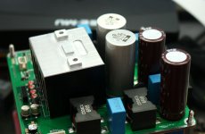
I think as long as the wires are kept as short as possible, it shouldn't be an issue. On the TI TPA3255EVM board, it looks like there is space on the bottom side to mount the Wurth inductors. This could be done by soldering short segments of wire to the two terminals of each inductor and feeding the wires into the through-holes where the stock Coilcraft inductors are mounted. I wonder why TI would determine that the Wurth inductors would perform better, yet design their EVM to use the Coilcrafts instead. This could be splitting hairs though, because I am enjoying the TPA3255EVM in stock form in my system.
Besides adding a pair of Altec Peerless 15335A input inductors to convert unbalanced RCA inputs to the differential (balanced) inputs of the TPA3255, I might try implementing the PFFB modification, which is easily accommdated on the TPA3255EVM PCB. I just need to try and dig my trusty Metcal soldering workstation out of storage.
There is no doubt that the TPA can be tweaked yielding a performance that is superior to the EVM.I wonder why TI would determine that the Wurth inductors would perform better, yet design their EVM to use the Coilcrafts instead. This could be splitting hairs though, because I am enjoying the TPA3255EVM in stock form in my system.
But I presume it is not the intention of TI to present an EVM with highest performance with best parts available on the market - but more a reference for high quality with affordable parts.
Personally I think the EVM performs quite good and I really doubt that any of our golden ears could notice the difference to a more sophisticated TPA3255 design.
The real question should be with the output inclusive feedback loop if the higher quality Coil Craft inductors still make any measurable or audible difference vs a lower cost inductor? Dr. Mord would seem to have this answer with his TPA3251 board development.
At pure resistive load, the advantage is very minor, especially at output levels below 10W. With complex loads, PFFB might control your speakers better, but this is something i haven't "tested".
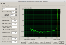
I.e. the actual board performance in PreFilter PBTL without an extra AFE and no PFFB is actually like so. (PVDD=30V, Load 5R, no heatsink:
10V = 25W
Plot taken by Voltwide. When using "low cost inductors" the advantage of PFFB is pretty obviously. Also/especially with TPA3118/TPA3128.
Attachments
Thank you Dr. It would seem you would still want to use a high quality output coil but with the PFFB circuit going to the best coils as found without the output inclusive circuit may be overkill? Would it make a difference between the Wurth and CoilCraft inductors with the PFFB?
As said (also by Voltwide), it is some kind of hairsplitting. PFFB might tighten the control of complex speakers/loads. You'd better ask Voltwide about this. If you need to get better by like 0.002% THD at 1kHz compared to the coilcraft, you may try.
Regarding the Wurth inductors, their advantage mostly come from physical dimension/construction. I actually use Codaca inductors in place, Voltwide is using Ferrocore. (Same geometry)

Regarding the Wurth inductors, their advantage mostly come from physical dimension/construction. I actually use Codaca inductors in place, Voltwide is using Ferrocore. (Same geometry)
Attachments
Last edited:
My modifications :
Filter :
1.
choke CoilCraft VER2923-103
2.
680nF EPCOS instead 470nF
3.
NE5532 instead TL072
4.
6 x Nichicon Fine Gold 10uF in the signal path instead 6x22uF
5.
LM2575HVS-15 instead LM2575S-15
6.
choke in the stabilizer 220uH (221) instead 22uH (220)
7.
2k instead 2.2k (stabilizer LM317)
8.
220uF (Low ESR) instead 22uF (LM2575HVS-15 - 15V, LM317 - 12V)
9.
capacitor PVDD
1500uF Panasonic Low ESR instead 3900uF Elna(???)
10.
10k 1% instead 10k 5%
From the latest PFFB application report, it can be seen that PFFB performance gain with good inductors is ~6dB, like bringing down 0.003% to 0.001%
http://www.ti.com/lit/an/slaa788/slaa788.pdf
Take note that some fact in the tables are labeled wrong.
http://www.ti.com/lit/an/slaa788/slaa788.pdf
Take note that some fact in the tables are labeled wrong.
sybic, I just received the same board as you have pictured. What did you do to stop the fault led and clip led from being on all the time. I see from your picture that you did not install the missing 3.3V regulator. I will also have to order the LM2575HV-15 as I plan to use +50Volt power supply.
I have a recollection that this question was asked (of an older TI chip) on the TI forums. My memory's a bit hazy but bigger caps lead to lower reliability due to electromigration. More capacitance makes for larger peak currents.
I found it. Thanks Abraxalito for the key word "electromigration" (whatever that means
 )
)Basically, its not recommended by Ti.
Larger bootstrap capacitor for TPA3122D2 - Audio Amplifiers Forum - Audio Amplifiers - TI E2E Community
- Home
- Amplifiers
- Class D
- TPA3255 - all about DIY, Discussion, Design etc