YouTube
Is this sound difference due to bad NE5532 op-amp ?
Have anyone tried AIYIMA TPA3251 Digital Audio Amplifier HIFI Power Amplifier 2.0 NE5532 175W *2 | eBay ?
They claims NE5532 can be replacable by OPA2604
Is this sound difference due to bad NE5532 op-amp ?
Have anyone tried AIYIMA TPA3251 Digital Audio Amplifier HIFI Power Amplifier 2.0 NE5532 175W *2 | eBay ?
They claims NE5532 can be replacable by OPA2604
A fake NE5532 is no NE5532. There is no good and bad NE5532. All real ones are high quality audio parts, which do not change the "sound" of any audio device, if implemented in the appropriate way.
There are situations where other OP-amps might fit better, because of load, power supply or what ever.
One additional point, the NE5532 is no "cheap" part, there are others that cost only a small fraction of it´s price. If you scrape off such a parts marking and print NE5532 at it, you will hear a difference, if your chain is good enough.
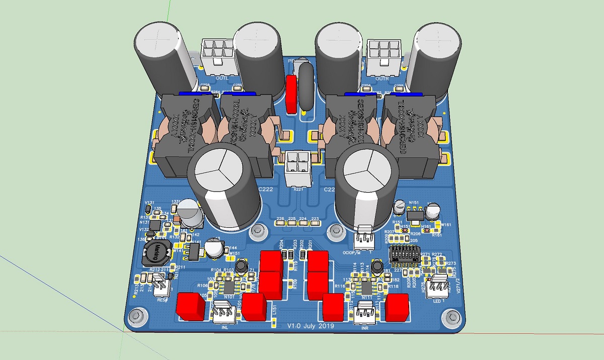
JPS64 and I have a new TPA3255 amp design here:
https://www.diyaudio.com/forums/gro...eference-design-class-amp-gb.html#post5869422
All options such as SE, BTL, PBTL available. SE or Balanced input, master/slave, adjustable frequency, etc all options remain.
Underside mounted chip eliminates separate heatsink by allowing chip to conduct to mounting panel.
Last edited:
3e Audio EAUMT-0260-2-A board
Hi,
as the 3e user's manual doesn't provide that amount of information as the TI TPA3255EVM manual, some questions are left:
Is there a schematics of the 3e board available anywhere?
How can it be cofigured for either unbalanced or balanced mode?
What's the reason for limiting the supply voltage to 51 Vdc instead of 53.5 Vdc that the chip allows per it's datasheet?
Best regards!
Hi,
as the 3e user's manual doesn't provide that amount of information as the TI TPA3255EVM manual, some questions are left:
How can it be cofigured for either unbalanced or balanced
There are 2 jumpers J3 and J4, one for each channel to set between single ended and differential inputs.
I just ordred just for fun the cheapes TPA3255 2.1 board. I payed 35$ shipping inlcuded.
I want to modd it. change outputfilter and SE capacitos.
I the datasheet the use 470uF capacitor but in the EVM the use big 1500uF.
What will happen if I take 330uF or bigger? I have 330uF 35V LXY for SE-output.
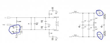
What is better:
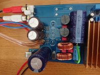
Left or right output. Left is from TAS5630 and right from TPA3255
I plan to use:
Wima MKS2-63V 1,0µF
Wima FKP2-250V 1,0nF or FKS2-400V 1,0nF
Wima MKP2-100V 10nF
Change SE output coil to 15uH
What do you thing about this modifications?
I want to modd it. change outputfilter and SE capacitos.
I the datasheet the use 470uF capacitor but in the EVM the use big 1500uF.
What will happen if I take 330uF or bigger? I have 330uF 35V LXY for SE-output.
What is better:
Left or right output. Left is from TAS5630 and right from TPA3255
I plan to use:
Wima MKS2-63V 1,0µF
Wima FKP2-250V 1,0nF or FKS2-400V 1,0nF
Wima MKP2-100V 10nF
Change SE output coil to 15uH
What do you thing about this modifications?
Attachments
Last edited:
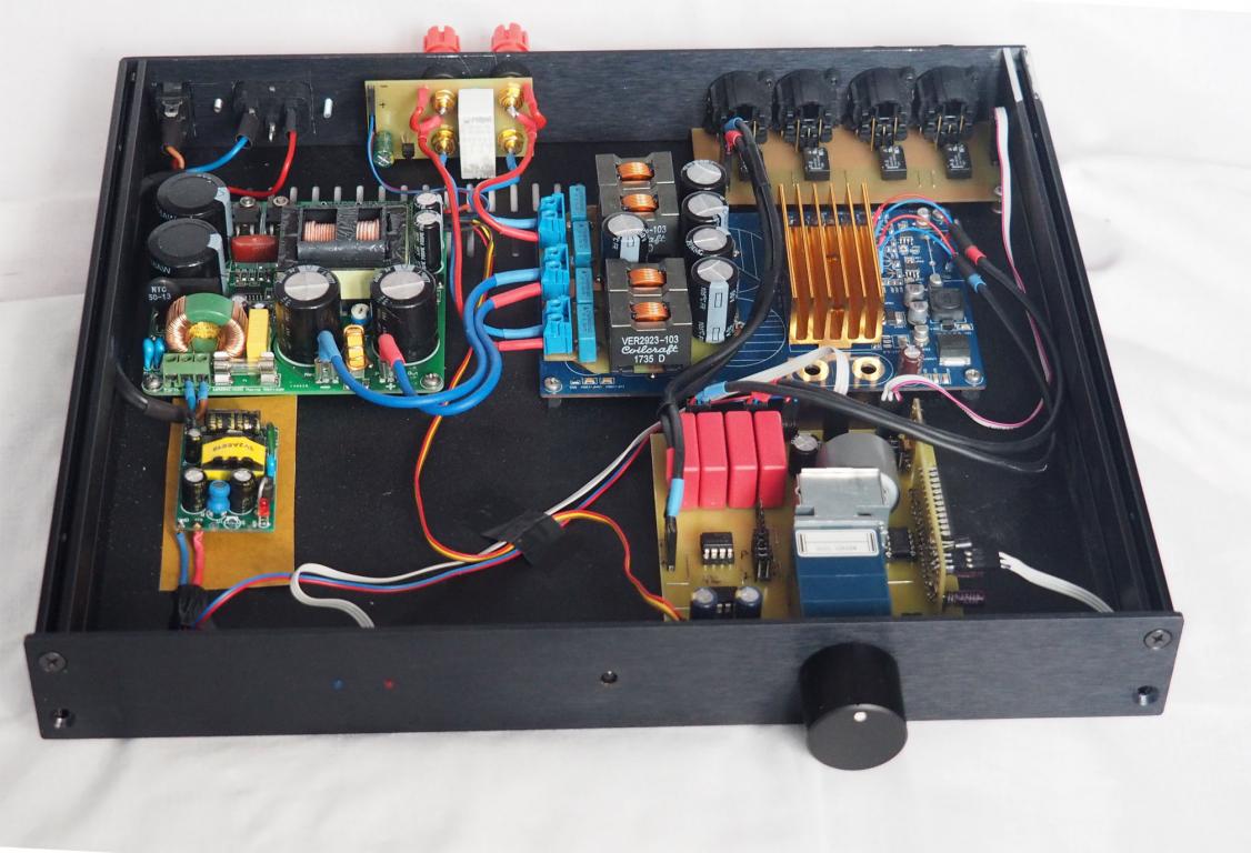
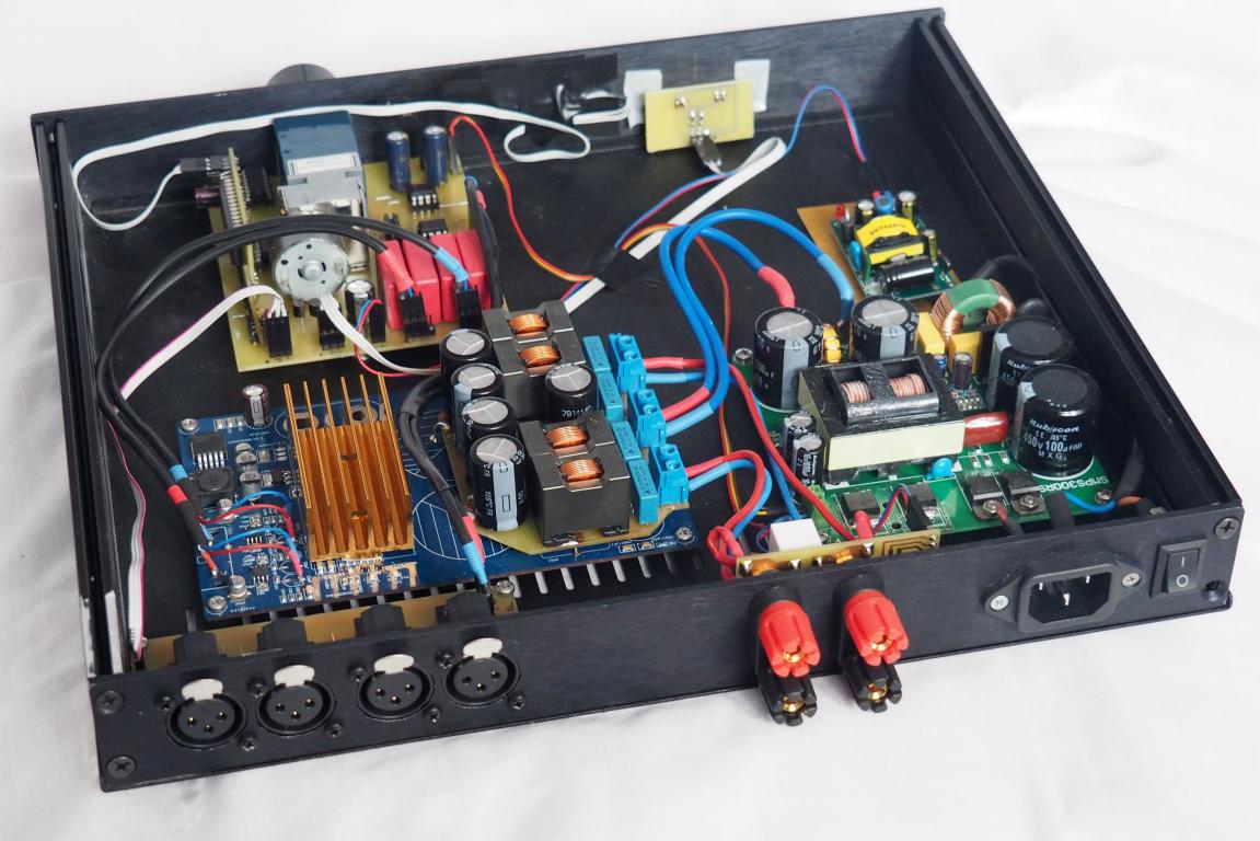
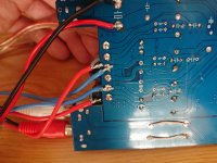
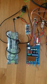
I made a full XLR, only two inputs.
I hooked directly on the input TPA3255
bypassing the pre amp
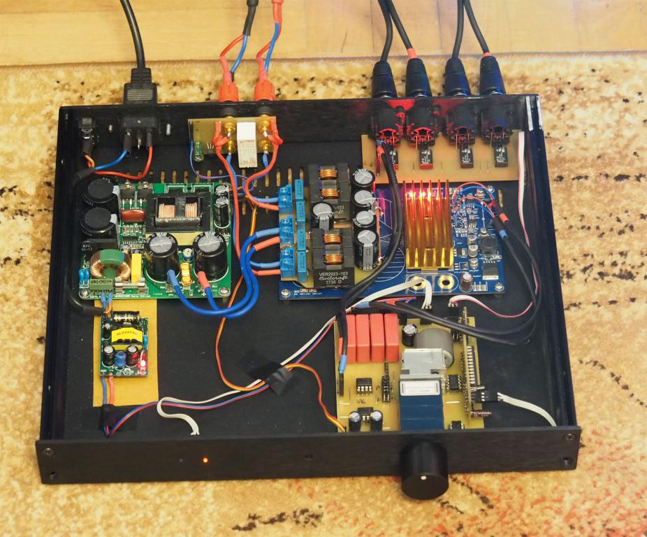
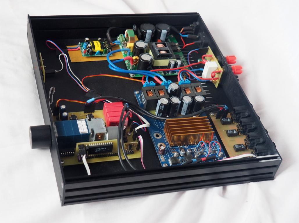
Hello Sybic nice neat work 🙂
Wold you mind to share where you got each board from ?
I'm trying to assemble few amps for my small self-made cinema room but I'm finding a bit difficult for a novice like me where to get all the boards from.
For example where did you got from the xlr input board?
thanks for all the help,
have a nice day,
Benedetto
Hi guys
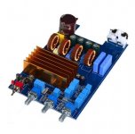
Did anyone try this eBay offering, seems like a complete amp w transformer, PSU and already built into an enclosure. I can’t see any heatsink so maybe they are using the enclosure to cool down the IC.
I’ve never heard the TI stuff but at $60 usd including shipping it’s very tempting unless you guys report that it’s a crappy design.
TPA3255 Bluetooth 5.0 HiFi Stereo Digital Class D DAC Decoder Amplifier Amp | eBay
Thanks
Eric
Hi guys
Did anyone try this eBay offering, seems like a complete amp w transformer, PSU and already built into an enclosure. I can’t see any heatsink so maybe they are using the enclosure to cool down the IC.
I’ve never heard the TI stuff but at $60 usd including shipping it’s very tempting unless you guys report that it’s a crappy design.
TPA3255 Bluetooth 5.0 HiFi Stereo Digital Class D DAC Decoder Amplifier Amp | eBay
Thanks
Eric
An old saying: If it looks too good to be true, perhaps it isn't true.
My comments:
The toroidal transformer, compared to the size of some other components, leaves the impression of being maximum 200VA. That means, the total output power steady state will not exceed some 180W and the values indicated are exaggerated or "music power".
I see no output filter chokes. For real TPA3255 they should be considerable in size. No filter chokes shown awakes my suspicion (could be on the rear side).
I see a BT-chip but no TPA3255 chip on the top-side. Perhaps on the rear side. Cooling to the metallic chassis is the only realistic option with a TPA3255 chip tugged away below but difficult to make work well due to very narrow tolerances.
How do you switch between the phono-input and the BT-source?
For the volume the markings are "MIN" and "MXA" (not MAX). Could be a reason for a good offer.
My impression - looks too good to be true (not a serious TPA3255 implementation).
The advertisement text hints uncritical copying from a TI TPA3255 datasheet without understanding of the values. One example: "Input Voltage: 30V-48V" - NO, not with a transformer in between.
Last edited:
@e_fortier
it looks to be an lm3886 amplifier. No coils on the pcb. You can find similar amp with typing lm3886 on ebay or ali.
it looks to be an lm3886 amplifier. No coils on the pcb. You can find similar amp with typing lm3886 on ebay or ali.
Yep, that would make sense. I see 2 IC near the end of the PCB, 11 pin each.
If it’s a GC I’ll pass. Been there done that ��
Thanks,
Eric
If it’s a GC I’ll pass. Been there done that ��
Thanks,
Eric
I think somewhere in here I read that Allo was was working on one. Given their track record I am hoping they come up with a good one.
Hello guys
Today I receive my TPA3255 2.1 Board.
I tested it with my bench power supply (max 32V). Stock its not bad. No bachground noise. Impressed... because I read in this thread that it can be bad.
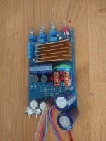
After short test I changed some caps and coils. I want to build it like datasheet.
Today I receive my TPA3255 2.1 Board.
I tested it with my bench power supply (max 32V). Stock its not bad. No bachground noise. Impressed... because I read in this thread that it can be bad.
After short test I changed some caps and coils. I want to build it like datasheet.
Attachments
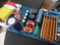
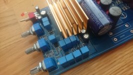
So i also change the capacitor of output circuit.
With all this modification I have 1nF 10nF and 1uF for filter and 1000uF decoupling capacitor. My new RLC meter is not arrived yet so I can not mesure stock coil.
Amp is driven with 40V from step up.
Works great. Party can start 🙂
With all this modification I have 1nF 10nF and 1uF for filter and 1000uF decoupling capacitor. My new RLC meter is not arrived yet so I can not mesure stock coil.
Amp is driven with 40V from step up.
Works great. Party can start 🙂
Attachments
Well, I can believe I found bunch of a fanatics as my self interested in building amps 😀
Howdy folks!! 😀
Hansueli, nice build up!
Tell me straight, could I use this board for building an amplifier for a car audio system?
I need a 4 channel amp (Pioneer GM-D8704) or go loony and bring in two TPA3255 boards (2.0 for Front and 2.1 Rear doors + SUB).
Just wondering how to get a audio signal from GX-204LE GU (Subaru Legacy 2007) head unit.... Solder in a RCA outputs or get a signal from speaker wires through a high low converter?
With the number of turns halved I would expect a quarter of the former inductance.Nanolized
It could be used in a car but you need powefull step-up.
For your GX-204LE GU you need to take a look on the internet.
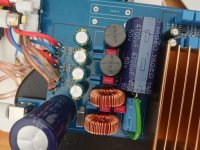
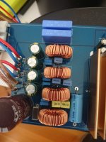
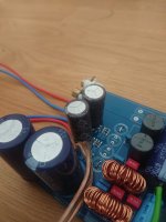
Today I mod the coils. I take same wire but half the amount of turn but paralleled the wire.
from approx 20uH and yet 10uH (measured with china LCR^^)
Voltwide nice to know. Amp works great.
I am impressed of quality. Bass is very strong.... I drive an HKTS200 subwoofer (broken amp)
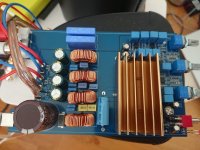
I desoldred the 5.5/2.1mm plug and could place another 4700uF cap. So I have 3 4700uF cap. Not the best I know but they where on my capa box.
I plan to change all caps from output with MKP2. On the dataheet and evaluation board the use only MKP for 1uF and not for the others. Is it not worse the money/changement?
What do you think about replace all 1uF caps for the OPAs? Because of the footprint only MKS will fit. Will it be the better way?
I am impressed of quality. Bass is very strong.... I drive an HKTS200 subwoofer (broken amp)
I desoldred the 5.5/2.1mm plug and could place another 4700uF cap. So I have 3 4700uF cap. Not the best I know but they where on my capa box.
I plan to change all caps from output with MKP2. On the dataheet and evaluation board the use only MKP for 1uF and not for the others. Is it not worse the money/changement?
What do you think about replace all 1uF caps for the OPAs? Because of the footprint only MKS will fit. Will it be the better way?
Attachments
- Home
- Amplifiers
- Class D
- TPA3255 - all about DIY, Discussion, Design etc