Hi,
if you're not interested in my, not quite so interesting, project you can skip to the Questions part far below, which are more or less generic and unrelated to this specific project.
If you want to point me to other chips / boards please do.
* Project :
i'm trying to put things together to turn some old cheap speaker sets into (cheap) active ones.
Please remember i'm looking for something cheap with decent sound, nothing fancy.
Those speaker sets are all 8ohms, no mention of power rating but the wide band speaker is rather large.
i will probably require 2x 30-50W to properly sonorize those rooms.
* Choices :
i'm looking at single power rail chips in order to simplify the power supply part, so i've chosen cheap TPA3116D2 or TDA7498(E?) chinese boards, maybe STA508 too.
I know there are quite a few other chips but i've narrowed down the choice to very low cost boards only, around 12e.
# Amplifiers :
- 1. TPA3116D2 (datasheet) YJ Blue Black Danzz design:
-> Board on Aliexpress
i picked that board because it's been very well documented (forum and datasheet) and hacked (DiyAudio TPA3116D2 Boards).
- 2. TDA7498 (datasheet) :
i picked that board for no particular reason other than the low price (also quite compact and has a vol pot).
-> Board on Aliexpress
other boards : -> one that looks nicer and -> one with connectors
I understand the TDA7498 should offer a little more power than the TPA3116.
The TDA7498E (datasheet) is also on my list if i ever need more power but the boards are more expensive, i also noticed the STA508 (datasheet) but haven't really looked into it..
# Power supply : i ended up with two choices and some optional tweaks
- 1. bare board 24v "4A to 6A"
i had no confidence in the rated specs but it turns out that little one can output a steady 3.8A without getting too warm, no significant problems at 5A with active cooling.
Ripple is acceptable and significantly lowered by adding a much larger output filtering cap (2x4700uF 16v in series, cheaper).
I also found a good review in russian of that board.
- 2. my other choice is any 19-20v laptop power brick rated at 4.74A.
- and some tweaks with dc-dc step up / step down boards :
-> "150W" uber cheap boost board aka "the creepy one"
-> "150W" better boost board (with fuse !)
-> "15A" step down board (probably not useful, i want to go up not down)
i must say i have not tested those dc-dc boards very much and i'd rather avoid using them.
* Questions :
I'm mostly trying to find out what will be, and set, the output power of the amplifier and properly match the power supply.
Unless otherwise stated, i will assume i'm using the 24V DC power supply board.
So reading the datasheets i usually try to follow the Output power vs Supply Voltage, and THD vs Power output curves.
The simple case is when there's an exact graph for my 8ohms load, in this case for the TDA7498.
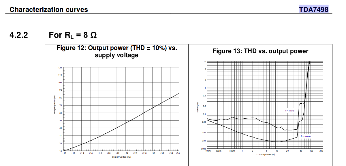
at 24V i should get around 45W.
2 things :
- Q1. Why is there a mention of THD=10% for this graph ?
Looking at the "THD vs Power" graph, i understand 10% THD happens at 85W which is supposed to be only with a 36V supply right ?
I know i'm missing something looking at the TPA3116 graphs below..
- Q2. is that the output power for the whole chip or per channel ?
Looking at the preview specs "8ohms 80w+80w @34v", i guess it's per channel.
Here are some curves for the TPA3116 :
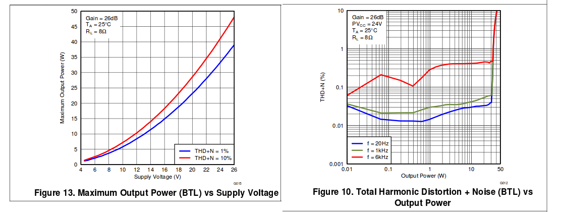
As i figured out there's a 1% THD Power vs Vcc curve so the one above should indeed be at 10%THD for 24v which is not wanted of course..
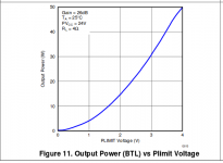
Then the TPA3116 has an interesting feature "PLIMIT" to set the max output voltage amplitude (lower than the max with the current supply voltage) and so limit the output power.

At least i know i can internally set the output power for that chip, i haven't seen the same feature with the TDA7498.
I don't know how the YJ Blue Black board is wired, my guess would be it's set for the max output power.
- Q3. So can i simply ignore all the details and get a fair estimate of the max output power of those chips by setting the power supply to a specific voltage ?
- Q4. Finally should i also take a closer look at the gain options, will that maximize the output power or should it be only set when you know the input level will be lower than the expected 1Vrms line level ?
In my case, the input will come from computer sound cards, so i'm expecting a fairly standard level.
thx for reading and for your comments
.eldon
Edit : links updated
if you're not interested in my, not quite so interesting, project you can skip to the Questions part far below, which are more or less generic and unrelated to this specific project.
If you want to point me to other chips / boards please do.
* Project :
i'm trying to put things together to turn some old cheap speaker sets into (cheap) active ones.
Please remember i'm looking for something cheap with decent sound, nothing fancy.
Those speaker sets are all 8ohms, no mention of power rating but the wide band speaker is rather large.
i will probably require 2x 30-50W to properly sonorize those rooms.
* Choices :
i'm looking at single power rail chips in order to simplify the power supply part, so i've chosen cheap TPA3116D2 or TDA7498(E?) chinese boards, maybe STA508 too.
I know there are quite a few other chips but i've narrowed down the choice to very low cost boards only, around 12e.
# Amplifiers :
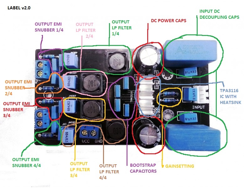
- 1. TPA3116D2 (datasheet) YJ Blue Black Danzz design:
An externally hosted image should be here but it was not working when we last tested it.
-> Board on Aliexpress
i picked that board because it's been very well documented (forum and datasheet) and hacked (DiyAudio TPA3116D2 Boards).
- 2. TDA7498 (datasheet) :
i picked that board for no particular reason other than the low price (also quite compact and has a vol pot).
-> Board on Aliexpress
other boards : -> one that looks nicer and -> one with connectors
I understand the TDA7498 should offer a little more power than the TPA3116.
The TDA7498E (datasheet) is also on my list if i ever need more power but the boards are more expensive, i also noticed the STA508 (datasheet) but haven't really looked into it..
# Power supply : i ended up with two choices and some optional tweaks
- 1. bare board 24v "4A to 6A"
i had no confidence in the rated specs but it turns out that little one can output a steady 3.8A without getting too warm, no significant problems at 5A with active cooling.
Ripple is acceptable and significantly lowered by adding a much larger output filtering cap (2x4700uF 16v in series, cheaper).
I also found a good review in russian of that board.
- 2. my other choice is any 19-20v laptop power brick rated at 4.74A.
- and some tweaks with dc-dc step up / step down boards :
-> "150W" uber cheap boost board aka "the creepy one"
-> "150W" better boost board (with fuse !)
-> "15A" step down board (probably not useful, i want to go up not down)
i must say i have not tested those dc-dc boards very much and i'd rather avoid using them.
* Questions :
I'm mostly trying to find out what will be, and set, the output power of the amplifier and properly match the power supply.
Unless otherwise stated, i will assume i'm using the 24V DC power supply board.
So reading the datasheets i usually try to follow the Output power vs Supply Voltage, and THD vs Power output curves.
The simple case is when there's an exact graph for my 8ohms load, in this case for the TDA7498.
at 24V i should get around 45W.
2 things :
- Q1. Why is there a mention of THD=10% for this graph ?
Looking at the "THD vs Power" graph, i understand 10% THD happens at 85W which is supposed to be only with a 36V supply right ?
I know i'm missing something looking at the TPA3116 graphs below..
- Q2. is that the output power for the whole chip or per channel ?
Looking at the preview specs "8ohms 80w+80w @34v", i guess it's per channel.
Here are some curves for the TPA3116 :
As i figured out there's a 1% THD Power vs Vcc curve so the one above should indeed be at 10%THD for 24v which is not wanted of course..
Then the TPA3116 has an interesting feature "PLIMIT" to set the max output voltage amplitude (lower than the max with the current supply voltage) and so limit the output power.
At least i know i can internally set the output power for that chip, i haven't seen the same feature with the TDA7498.
I don't know how the YJ Blue Black board is wired, my guess would be it's set for the max output power.
- Q3. So can i simply ignore all the details and get a fair estimate of the max output power of those chips by setting the power supply to a specific voltage ?
- Q4. Finally should i also take a closer look at the gain options, will that maximize the output power or should it be only set when you know the input level will be lower than the expected 1Vrms line level ?
In my case, the input will come from computer sound cards, so i'm expecting a fairly standard level.
thx for reading and for your comments
.eldon
Edit : links updated
Attachments

Last edited:
Generally: you understood it well, did a good research. Limiting below maximal output usually gives higher subjective overdrive performance, so if you have margin, try this way! Otherwise everything is correct, and I cant give you any specific advice without further investigation. A small notice: giantic DC decoupler foil capacitors are unneccessary (I mean much smaller ones can be as good or better), but OK.
...
- Q1. Why is there a mention of THD=10% for this graph ?
Looking at the "THD vs Power" graph, i understand 10% THD happens at 85W which is supposed to be only with a 36V supply right ?
I know i'm missing something looking at the TPA3116 graphs below..
- Q2. is that the output power for the whole chip or per channel ?
Looking at the preview specs "8ohms 80w+80w @34v", i guess it's per channel.
...
A lot of chip makers rate their amps at 10% to give higher numbers.
I try to use the 1% or 0.5% if possible. Those graphs are usually available.
Think back a few years ago when computer speakers started being rated a 300Wpmpo.(example) The IC used was a 1Wrms/ch device.
Output is usually per channel.
OPINION WARNING:
I like the TPA3116. Supply 4.5V to 26V. Used it in BTL and PBTL.
The TDA7498, TDA7498L, TDA7498MV, TDA7498E all have different "Overcurrent protection threshold". Recommended 14V-36V operation. But I have not used it or researched it. If I did I would go for the "E" version.
The STA508 is a "40V 4.5A QUAD POWER HALF BRIDGE" so there will be design circuitry surrounding it. That is why there are no distortion graphs in the data sheet...They don't know what you are going to do with it. (It might be OK, but I would avoid it.)
")
thx for your comments
Although from my sound tests and reading the forum, i find that replacing the stock 0.47uF EPCOS (are those genuine epcos caps or fake ones ?) from the YJ board, with basic 1uF ones, does improve the low frequency response of the circuit.
Anyways back to my research.
i've been reading the TPA3116 thread and in particular the PLIMIT feature of that chip.
I thought it would ensure limiting distortion but it looks like it's only power output related.
But at the same time the comments discussed quite a bit the amp gain so i tried to apply what i understood to my 24V supply.
- from the datasheet if Plimit is not set (or set to max), the max output voltage is 17.9Vrms (24v Vcc / 26db gain / 1Vrms input).
So apparently there's some losses (~10%) involved in the output voltage, compared to a set gain level, wich here should give 19.95Vrms.
But 17.9Vrms into 8ohms (assumed from the Po vs VCC curve) load gives 40Wrms. And apparently that would be at 10%THD.
Q1 : according to the datasheet, with Vcc = 24V, Vout = 17.9Vrms = 25.31 Vpeak.
Is it possible to get a peak output voltage above the supply voltage ?
Q2 : Then what's more interesting i think is the matter of gain and input voltage.
i haven't made any measurements yet but what kind of voltage should i consider for the audio line signal, mostly computer soundcards ?
From wikipedia :
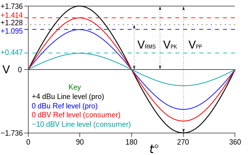
if the consumer electronics line level is actually -10dBV (0.447Vpeak) and as the YJ board has a 26db gain, then Vout should be 6.3Vrms (ignoring the losses mentioned above) which would then only produce 5Wrms (into 8ohms) ???
Q3 : The other thing i don't quite get is how rising the supply voltage by itself is enough to boost the output power ?
(with a fixed input voltage gain)
Is there a relationship between the gain and supply voltage that i missed from the datasheet ?
I'll definitely try to get some readings from my boards, all of this is quite confusing.
i think i get what you mean. i've seen those crazy mods with great looking (possibly sounding too) caps.A small notice: giantic DC decoupler foil capacitors are unneccessary (I mean much smaller ones can be as good or better), but OK.
Although from my sound tests and reading the forum, i find that replacing the stock 0.47uF EPCOS (are those genuine epcos caps or fake ones ?) from the YJ board, with basic 1uF ones, does improve the low frequency response of the circuit.
Anyways back to my research.
i've been reading the TPA3116 thread and in particular the PLIMIT feature of that chip.
I thought it would ensure limiting distortion but it looks like it's only power output related.
But at the same time the comments discussed quite a bit the amp gain so i tried to apply what i understood to my 24V supply.
- from the datasheet if Plimit is not set (or set to max), the max output voltage is 17.9Vrms (24v Vcc / 26db gain / 1Vrms input).
So apparently there's some losses (~10%) involved in the output voltage, compared to a set gain level, wich here should give 19.95Vrms.
But 17.9Vrms into 8ohms (assumed from the Po vs VCC curve) load gives 40Wrms. And apparently that would be at 10%THD.
Q1 : according to the datasheet, with Vcc = 24V, Vout = 17.9Vrms = 25.31 Vpeak.
Is it possible to get a peak output voltage above the supply voltage ?
Q2 : Then what's more interesting i think is the matter of gain and input voltage.
i haven't made any measurements yet but what kind of voltage should i consider for the audio line signal, mostly computer soundcards ?
From wikipedia :
if the consumer electronics line level is actually -10dBV (0.447Vpeak) and as the YJ board has a 26db gain, then Vout should be 6.3Vrms (ignoring the losses mentioned above) which would then only produce 5Wrms (into 8ohms) ???
Q3 : The other thing i don't quite get is how rising the supply voltage by itself is enough to boost the output power ?
(with a fixed input voltage gain)
Is there a relationship between the gain and supply voltage that i missed from the datasheet ?
I'll definitely try to get some readings from my boards, all of this is quite confusing.
Hi,
- and some tweaks with dc-dc step up / step down boards :
-> "150W" uber cheap boost board aka "the creepy one"
You may want to tweak this boards and/or change the inductor if you need big step-up-ratios.
Been there, done that -> documented here:
10/30/50/100W LED application driver (UC3843A). #360customs
...
Q1 : according to the datasheet, with Vcc = 24V, Vout = 17.9Vrms = 25.31 Vpeak.
Is it possible to get a peak output voltage above the supply voltage ?
...
No, that is where the 10% distortion is coming into play...the amplifier is clipping the sine wave and that results in more equivalent power.
...
Q3 : The other thing i don't quite get is how rising the supply voltage by itself is enough to boost the output power ?
(with a fixed input voltage gain)
Is there a relationship between the gain and supply voltage that i missed from the datasheet ?
...
Higher supply voltages will not increase power with a specific drive level.
Higher supply voltages will allow more (un-clipped) power with increased drive.
Example:
Lets say that 1V of drive gets "X" watts with a 12V supply (no clipping) and trying to put 1.1V of drive will start to clip the output and produce a distorted waveform.
Further increase in drive of 1.5V will clip and distort even more.
But if you increase the supply (while driving at 1.5V) to 24V then the amplifier will have enough output swing to produce the increase in power without clipping. 2.25 * "X" watts.
You may want to tweak this boards and/or change the inductor if you need big step-up-ratios.
Been there, done that -> documented here:
10/30/50/100W LED application driver (UC3843A). #360customs
thx i'll check it out but if i need to use a step up, it will be for the TDA7498 and it should only go from 24v to 28v probably.
I do understand the coil has a major role in that step up circuit and those boards use cheap components, unfortunately coils are quite expensive so replacing them may not be a priority for this project.
Also i'm not quite sure why this guy made a constant current mod, there's a version of that circuit with constant current, but that's the fun of it i guess.
-4 dB is just an approximate usage value. Most standalone sound card gives up to 6 dB output.
Yeah this is not a respected standard apparently.
I've measured my desktop soundcard line output, with a 1KHZ sine wave generated in audacity (amplitude of "1") and main volume at 100%, i get 1.26Vrms on my multimeters.
So it's more like +4dBu "pro level" than consumer electronics.
With the soundcard main level maxed out (over 100%) the voltage goes as high as 1.73Vrms, probably completely distorted.
No, that is where the 10% distortion is coming into play...the amplifier is clipping the sine wave and that results in more equivalent power.
okay i kind of get it, i was expecting clipping above the supply rail but i still don't understand how the datasheet comes up with 17.9Vrms output voltage for the 24V supply.
I imagine that you can achieve higher power output levels when you introduce clipping.
Actually the datasheet says so in the plimit examples : "POUT (10%THD) = 1.25 × POUT (unclipped)"
Higher supply voltages will not increase power with a specific drive level.
Higher supply voltages will allow more (un-clipped) power with increased drive.
Okay that's what i understood then, thx.
Well there's not much room for tweaking, with a 24V supply, i will achieve a maximum (? the curve goes up to 50W somehow) of 40W (10%THD, 17.9Vrms Vout @ 8ohms) per channel.
2x30W with around 0.5% THD @6KHz, not sure it'll be enough..
Efficiency at that level with my load should be 92% which would then require 87W from the power supply. Even with some margin, if that efficiency figure is not exact, it should be well within the power supply capability.
And at that level distortion will be so high that i shouldn't ever be used.
The only thing that could be done is to set the gain to the lower setting (20db), in order to avoid reaching distortion levels.
But then my maximum output power with a +4dBu line level would fall below 2x20Wrms.
Q: Do you have to use the defined resistance values and gain levels or can i plot a line to try setting other gain levels ?
(between 20 and 26dB)
And one last question, does the gain only matter for the max Vout amplitude or does it also influence other characteristics of the amplifier, frequency response and so on ?
...
Q: Do you have to use the defined resistance values and gain levels or can i plot a line to try setting other gain levels ?
(between 20 and 26dB)
And one last question, does the gain only matter for the max Vout amplitude or does it also influence other characteristics of the amplifier, frequency response and so on ?
Gain selection is not a linear function. The IC reads the value and selects one of 4 choices. (TPA31116)
Choice of gain affects input impedance. (at least on the 3116) Check the data sheet.
Choice of gain does not affect max Vout...it affects how much drive you need to get that max Vout.
Some people have made the statement that the gain setting affects the "sound" of the amplifier. I have not investigated this so have no data to form an opinion.
eldonT, i used to implement the constant current mod to use them as a LED driver. Of course, not needed here. While implementing this, it had be seen that the whole implementation of this step up circuit is not optimal if it comes to high step up ratios. It works but won't give the maximum power and stresses the parts used a lot. This all can be seen from the simulations and measurements. It isn't made for doing 10V to 36V at more than 30W with the inductor supplied. Doing so results in a a lot of heat and high ripple. As an amp is more of a dynamic load, you may won't notice. Those boards with CC mod in place use an additional opamp for current sensing, but it is possible to do without.
So yes, the investigations were mostly driven by the fun part and to see if there's room for boosting the stock performance with lowest budged. It can easily be adapted to other implementations.
So yes, the investigations were mostly driven by the fun part and to see if there's room for boosting the stock performance with lowest budged. It can easily be adapted to other implementations.
- Status
- This old topic is closed. If you want to reopen this topic, contact a moderator using the "Report Post" button.
- Home
- Amplifiers
- Class D
- Reading datasheets, output power limit, THD, gain..