Hi,
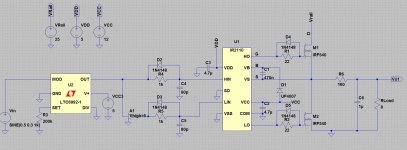
I need to design a Class D for a school assignment, but I'm having trouble simulating the IR2110 for the H-bridge. I keep getting the message "Time step too small; time = 4.42242e-005, timestep = 1.25e-019: trouble with u1:diode25-instance d:u1:_md5_d1"
Does anyone know how can I solve this or what does it mean?
Thanks!
Hi Nick,
Typically a timestep too small means the simulation could not converge upon a reasonable answer. This is a transient simulation and the simulation is taking smaller and smaller steps to estimate the node currents and voltages. If it can't converge it spits out this error. Unfortunately that means there's something in the circuit that is wrong, but could typically be anything.
I would check the schematic and watch out for some of the following items:
- every node has two connections
- no parallel inductors
- each branch has some resistance associated with it, Ideal items don't simulate as well
- dc path at every node
- reduce rise/fall times of any sources
The error seems to hint that you are having trouble with a diode. You may want to double check the mode you are using. You can also try modeling the subcircuit without the diode.
Most simulators will also have alternate simulation methods you can try. (Essentially uses a different algorithm to populate the next points).
Good luck,
Scott
Without the schematic and probably the settings it is practically meaningless. Share it!Hi,
I need to design a Class D for a school assignment, but I'm having trouble simulating the IR2110 for the H-bridge. I keep getting the message "Time step too small; time = 4.42242e-005, timestep = 1.25e-019: trouble with u1:diode25-instance d:u1:_md5_d1"
Does anyone know how can I solve this or what does it mean?
Thanks!
Simulation of ClassD is generally very dificult. Smart simplifications can make it easier. There are some simulators designed and parametered for this specific reason.
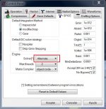
Thanks for the reply! I think I might found a solution. I changed the solver to Alternate and now it's not showing the error anymore. But the simulation takes a long time to complete. I'll attach the circuit I'm trying to simulate.
Pafi, can you please tell me what kind of simulator can I use for this?
Also, is there an easier way to generate a PWM instead of using an IC?
Pafi, can you please tell me what kind of simulator can I use for this?
Also, is there an easier way to generate a PWM instead of using an IC?
Attachments
Thanks for the reply! I think I might found a solution. I changed the solver to Alternate and now it's not showing the error anymore. But the simulation takes a long time to complete. I'll attach the circuit I'm trying to simulate.
Pafi, can you please tell me what kind of simulator can I use for this?
Also, is there an easier way to generate a PWM instead of using an IC?
Tina has a free version distributed by Texas Instruments, this is good for ClassD, but has limited modell base (no IR ICs, since its a competitor of TI). You can use UCC27200, I think its even better, if 100 V is enough.
Generating PWM in real life, or in simulation? In real life IC is the simplest. In simulation you can compare a tiangle wave to the modulation signal, which can be done by an ideal voltage controlled switch + 1 resistor.
BTW: your schematic is not really a ClassD audio amplifier, but a heater. ;-)
- Status
- This old topic is closed. If you want to reopen this topic, contact a moderator using the "Report Post" button.