Hi all,
I'm curious to see if anyone on this forum has tried to build (from scratch) a SMPS power supply for use in a power amp, that would be powered from the line.
There are a few threads on SMPS supplies for use in cars, where it is an unavoidable solution, but I have not seen anything line-powered being discussed. Of course, such an amp built on a DIY basis would really be something out of the ordinary.
Needless to say, this would not be a beginner's project, and I am personally not about to start on something like that right now, but it's interesting to think about what components that would be needed, how to build something that would be safe to use whilst delivering high power, and so on. The goal would be a supply of, say, -60-0-60V at high current.
The U.S company QSC and the swedish LABGruppen both successfully market high power amps with switchmode power supplies, and QSC are nice enough to have schematics on their web page, also for current designs.
The QSC switchmode supply (for their PLX series) is surprisingly simple. They use a SG3525 pulsewitdh modulator to make two very rugged IGBTs drive a transformer in a push-pull configuration. The secondary side use one fast diode bridge per rail, and HF filtering is done using ferrite beads. No details on the transformer are included in the schematic.
I have a source for an iron powder toroid, Amidon T-400A-26, which is rated for 0-1MHz operation. This is 101 mm across and 33 mm high, with a 57mm hole in the middle. The cross-section is 743 mm2.
Maybe this could be used to wind a transformer? If you know that this is a case of 'forget it', then please reply and say so.
Otherwise, does anyone have a good hint on where to find info on calculating windings? What power could one hope for with the above toroid (which is quite big for a switchmode application). What frequency should one aim for? (This appears to be limited by the IGBTs).
Cheers,
Marcus
Offline converters are not for the weak of heart. You're dealing with 170 VDC or so on the primary side, and you can't connect a 'scope anywhere because the mains are not at common negative.
That said, it's done all the time in PC power supplies. They're a good place to steal high voltage electrolytics, transistors, bridge rectifiers, and even a core.
I can't comment on the core you have.
That said, it's done all the time in PC power supplies. They're a good place to steal high voltage electrolytics, transistors, bridge rectifiers, and even a core.
I can't comment on the core you have.
Hi Marcus!
Checking the limits what is allowed in this forum ;-) ?
....no discussion about circuits operated at mains...!
You can contact me directly through mail
[[EMAIL ADDRESS REMOVED BY MODERATOR]]
But I did not find the schematic which you have mentioned.
So for discussion I would need this or the direct link.
And some days patience as I am running low on time these
days.
But please note. For such a design you do not only need the
design of the magnetic behaviour itself, but the transformer also must comply with the relevant safety standards. They typically define min required creepages, thickness of isolation, number of required isolation layers, test voltages,... fire retarding materials (UL-listing??)..... and more... !!!!
Also the equipment for working with SMPS at mains may not be
with you... differential probes, isolated current probes (?)....
And then the parasitic effects of the layout.....
If you only have the schematic, you will need a good portion of
SMPS-Design know how to get that thing running in proper way.
And in fact I would not encourage you for such experiments.
Last but not least: Do you plan to watch TV, or listen to the radio
when this SMPS is operating? ...have fun with some Voodoo-like EMI phenominas...
Cheers
Markus
Hi again,
I'm sorry if my post above was against the rules! I did check the forum rules and moderator's statement, and assumed the subject to be OK, but if discussing a SMPS is not allowed, I apologize!
I would not think of trying to design something like that without a plethora of safety precautions, such as an isolation transformer, for starters, and for now I just brought it up as a purely theoretical idea.
Anyway, thanks for the responses. I do not know if QSC still have the schematics online, as I downloaded them some time ago. Anyway, I did not suggest making a direct copy of their design, but rather that their schematics could be an inspiration.
Marcus
I understand and appreciate the prohibition about circuits
on the AC line, but realistically, just about all these projects
have to deal with the AC line at some point. A DIYer can
fry himself wiring up a transformer, switch, fuse, filter, and
AC inlet.
It is also easily possible for power amps isolated from the AC
line to deliver lethal voltages, inside and at the output terminals.
I don't have an answer to this, but a blanket prohibition may not
be the best it.
Go to www.ti.com and search for SEM800, then search for 100's above and below that. You will find a lot of information. Also, application notes at www.linear.com are quite informative. There is also an extremely interesting/useful app note from www.infineon.com
You can also purchase eval boards to get going quickly.
Petter
You can also purchase eval boards to get going quickly.
Petter
Iron powder cores are not suitable for magnetic coupling transformers due to its low permeability [mu=50 or so] that would require a huge number of turns and therefore huge leakage inductances
For your purpose, you need low permeability power ferrites [mu=2500 or so], higher permeability ferrites [mu=10.000] are more suitable for signal transformers
Low loses in the core up to high frequencies [>1Mhz] are not required except when you use high switching frequencies [>200Khz], for 30-100Khz most power ferrite materials are suitable [to get an idea, look for 3C85 and 'equivalents']
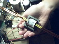
As an example, in the attached picture you can see a transformer with ferrite core that I use in one of my designs [It's something like an EE 42, In my country I can only get this kind of 'no-name' stuff at reasonable prices]
Windings are designed to operate at 31Khz [pretty slow for today standards but allows to use cheap bipolar transistors for switching and still get low losses, 4x MJE18008] and to mantain 1KW output [14,4V 72A regulated] with little air cooling [less than 8 watts losses in the copper]
Secondary consists of to layers, each with a 4-turn winding made witn 5x 1mm diameter wire and is sandwitched by two layers of primary with 24-turns made witn 1mm wire [sandwitching reduces leakage inductance to 8uH as seen from the primary side with shorted secondaries]
Insulation between primary and secondary in this prototype consists of 3 layers of common insulating tape [I can't find the usual mylar tape in my country] and wires are protected with PVC tubing when they enter and leave the bobbin
To saturate this transformer you need to apply more than +-360V square wave to the primary at 30Khz and 25ºC, this is the main criteria to select its number of turns. I use to avoid calculations and do it empirically, measuring current versus volts*time/turns curves and selecting a good compromise [50 to 70% of the value needed to saturate the core at 25ºC since at higher temperatures the core saturates faster]
Knowing a valid number of primary turns for your application, then you can select secondary turns for your desired turn ratio [more primary turns means more leakage inductance, ie: more time [lost] needed to reach the desired current with given voltage applied to primary and load to the secondary, about 200nS for this design]
PD: Anybody could suggest me a cool forum where switching knowledge could be freely shared? I feel this board is not the right place for serious switching discussion and power conversion has evolved a *lot* since 50-60Hz 'passive' switching
For your purpose, you need low permeability power ferrites [mu=2500 or so], higher permeability ferrites [mu=10.000] are more suitable for signal transformers
Low loses in the core up to high frequencies [>1Mhz] are not required except when you use high switching frequencies [>200Khz], for 30-100Khz most power ferrite materials are suitable [to get an idea, look for 3C85 and 'equivalents']
As an example, in the attached picture you can see a transformer with ferrite core that I use in one of my designs [It's something like an EE 42, In my country I can only get this kind of 'no-name' stuff at reasonable prices]
Windings are designed to operate at 31Khz [pretty slow for today standards but allows to use cheap bipolar transistors for switching and still get low losses, 4x MJE18008] and to mantain 1KW output [14,4V 72A regulated] with little air cooling [less than 8 watts losses in the copper]
Secondary consists of to layers, each with a 4-turn winding made witn 5x 1mm diameter wire and is sandwitched by two layers of primary with 24-turns made witn 1mm wire [sandwitching reduces leakage inductance to 8uH as seen from the primary side with shorted secondaries]
Insulation between primary and secondary in this prototype consists of 3 layers of common insulating tape [I can't find the usual mylar tape in my country] and wires are protected with PVC tubing when they enter and leave the bobbin
To saturate this transformer you need to apply more than +-360V square wave to the primary at 30Khz and 25ºC, this is the main criteria to select its number of turns. I use to avoid calculations and do it empirically, measuring current versus volts*time/turns curves and selecting a good compromise [50 to 70% of the value needed to saturate the core at 25ºC since at higher temperatures the core saturates faster]
Knowing a valid number of primary turns for your application, then you can select secondary turns for your desired turn ratio [more primary turns means more leakage inductance, ie: more time [lost] needed to reach the desired current with given voltage applied to primary and load to the secondary, about 200nS for this design]
PD: Anybody could suggest me a cool forum where switching knowledge could be freely shared? I feel this board is not the right place for serious switching discussion and power conversion has evolved a *lot* since 50-60Hz 'passive' switching
Attachments
As an applications engineer that works with SMPS all the time at power levels from 5w to 3kW, just a few points to suggest:
1. ALWAYS use an isolation setup for testing- at the least, a 120VAC:120VAC isolation transformer with fusing or circuit breaker, but if you can find something like an active inverter wtih protection functions like a Cal Instruments supply, that is even better, as you can test at varoius voltages and frequencies (Europe vs. USA, for example).
2. There are many standard references by authors like Abraham Pressman, Kit Sum, etc., on SMPS design; do a google search, take a look, and pick one that seems at your level to start. Even Borders and Barnes and Noble carry such books in their technology section.
3. As Petter suggested, Unitrode/TI references are good, and if you download their app notes, you'll have an interesting starting point.
4. Magnetics Inc. has a wide range of core products for SMPS, including Ferrite cores for transformers and MPP/Kook Mu cores for inductors. They have design calculation software also to help streamline the process. I did a 1 kW resonant reset forward convereter with a new HV SiC switch over the Xmas holidays (some holiday, huh?), and their site made it much easier to select the right parts and get the work done than most.
5. Simulation with a good simulator is a wise idea before you buy your first resistor or core. I've used most of the available ones in the business. (PSPICE, HSPICE, SABER, SPECTRE, SSPICE, IS-SPICE). One of the best performing ones is SIMetrix from Catena Software, UK; their Intro version of 4.5 will simulate a complete forward converter quite well; very stable and free from convergence issues, and MUCH, MUCH easier to use than current or past versions of PSPICE. They have reasonably good built in vertical MOSFET model, and good nonlinear magnetics models. The "paid for" versions are reasonably priced, though out of the range of casual DIY....")
SIMetrix
That said, SMPS design is not for the faint of heart, or someone who isn't really an engineer at heart, if not on paper. Just the EMC issues make people crazy....
Be safe, and have fun. If you can't get a SIM to work, don't worry about building the hardware....
Best regards,
Jon
1. ALWAYS use an isolation setup for testing- at the least, a 120VAC:120VAC isolation transformer with fusing or circuit breaker, but if you can find something like an active inverter wtih protection functions like a Cal Instruments supply, that is even better, as you can test at varoius voltages and frequencies (Europe vs. USA, for example).
2. There are many standard references by authors like Abraham Pressman, Kit Sum, etc., on SMPS design; do a google search, take a look, and pick one that seems at your level to start. Even Borders and Barnes and Noble carry such books in their technology section.
3. As Petter suggested, Unitrode/TI references are good, and if you download their app notes, you'll have an interesting starting point.
4. Magnetics Inc. has a wide range of core products for SMPS, including Ferrite cores for transformers and MPP/Kook Mu cores for inductors. They have design calculation software also to help streamline the process. I did a 1 kW resonant reset forward convereter with a new HV SiC switch over the Xmas holidays (some holiday, huh?), and their site made it much easier to select the right parts and get the work done than most.
5. Simulation with a good simulator is a wise idea before you buy your first resistor or core. I've used most of the available ones in the business. (PSPICE, HSPICE, SABER, SPECTRE, SSPICE, IS-SPICE). One of the best performing ones is SIMetrix from Catena Software, UK; their Intro version of 4.5 will simulate a complete forward converter quite well; very stable and free from convergence issues, and MUCH, MUCH easier to use than current or past versions of PSPICE. They have reasonably good built in vertical MOSFET model, and good nonlinear magnetics models. The "paid for" versions are reasonably priced, though out of the range of casual DIY....
SIMetrix
That said, SMPS design is not for the faint of heart, or someone who isn't really an engineer at heart, if not on paper. Just the EMC issues make people crazy....
Be safe, and have fun. If you can't get a SIM to work, don't worry about building the hardware....
Best regards,
Jon
Eva said:PD: Anybody could suggest me a cool forum where switching knowledge could be freely shared?
I would also love to know as well, tho. my primary interest is in either adapting ATX PS for audio applications or expansion around LM simple switcher chips.
I have been experimenting with them for years and think it is possible to be careful. If you want to use less voltage, you can run a totem pole (half bridge) off of 160 volts. That keeps the primary voltages down to half what they would be otherwise. You just sacrifice some efficiency in certain cases, but that can be compensated for by designing-in a higher current primary side.
(maylar) Offline converters are not for the weak of heart. You're dealing with 170 VDC or so on the primary side, and you can't connect a 'scope anywhere because the mains are not at common negative.
This is true of course unless you use an Isolation tranformer (1:1) for testing purposes only. If you do not have one You can use Two back to back Step-down Transformers in series IE: Two 120v - 12v secondaries tied together so as to have 120v - 120v Isolated from ground.
hi subwo1,
i make a living out of repairing pc psu's, i have done HEC's And Enermax and ANTEC pc psu's, lots og generics too...the generics i do modding by replacing parts with higher capacity ratings and the impact i would say is dramatic specially for the cheaper psu's.
i would be happy if there is a permanent thread regarding smps on this website....
i have a question for you, i dismantel some of the traffos and i find some with gaps in the center leg, while others do not have, can you differentiate between the two? i understand the gap is there to avoid core saturation, but i would like to know the effect of the gap on power delivery if any...
thanks a lot in advance...
i hope to be able to rig up oone of my own pc psu someday....i am not in a hurry as i realize i have lots to learn, repairing is easy, but designing ang building one from the ground up is another .... i have a collectiion of 3c85 type cores which i understand to be good up to 200khz...
Hi joan2,
Those cores probably are gapped because the topology is push-pull. That approach tends to place a DC bias on the transformer which causes heating and a tendency to saturate. I have noticed the heating problem to be somewhat severe on ungapped cores I tried to use for push-pull.
Those cores probably are gapped because the topology is push-pull. That approach tends to place a DC bias on the transformer which causes heating and a tendency to saturate. I have noticed the heating problem to be somewhat severe on ungapped cores I tried to use for push-pull.
Ferrite cores are gapped to reduce its high permeability and allow some energy to be stored in the air and not just all the energy in the core
I think that the most easy way to understand this is to apply constant volts/turns to the core, while measuring the current waveform in the coil, and when current gets too high let the coil freewheel and return to the supply all the energy it has stored [>10Mhz dual oscilloscope is mandatory and digital storage is a great thing to analyze curves without the circuit running]
Provided the vots / turns is keep constant, the sloppe of the current / time curve is nothing but the inverse of the inductance shown by the core for that current [all non-air-cored inductors have variable inductance depending on current]
As current increases, inductance suddenly changes from the high value given by the core permeability to the low value given by the coil itself as there were no core [leakage inductance].
This is called 'saturation'. It ocurrs when the core is 'full' of energy and its permeability suddenly decreases and can be easily seen as a knee in the current waveform [past this point, the core must be switched off quickly to prevent the current to rise without control]
The curves for ungapped cores show very high [magnetizing] inductances and very low saturation currents, so its main use are magnetic couplings where you expect the transformer to act as an ideal transformer capable of directly transferring long pulses of energy between windings, storing very little energy in the core itself
Examples of magnetic couplings are push-pull magnetically-coupled buck converter topologies used in AT & ATX PC power supplies and other medium or high applications [>200W]
As you progressively increase the gap, you can see how the [magnetizing] inductance decreases and the saturation current increases
If you try to calculate total stored energy for different gap lenghts [E = .5 * L * I^2] you can see how the value increases as gap increases, but the relationship appears to be very complex [not linear nor quadratic]
This means that cores are gapped to use them as inductors, whose energy storage capability, inductances and saturation currents can be adjusted with gap lenght and number of turns
Since the ferrite is still showing much higher permeability than if there were no core, gapped cores require much less turns to achieve the same inductance as an air cored inductor, and therefore, they provide lower leakage inductance between coils, allowing them to be used as thight coupled inductors
The most ussual application for coupled inductors are flyback converters, the standard topology for low power [<100W] supplies [VCR, DVD, TV, monitors, PlayStation, battery chargers, low power or standby section of AT & ATX, etc...]
The flyback topology is very demanding on leakage inductance since the energy is stored in the core through the primary and then it's released through the secondaries, so gapped coupled-inductors designed to have good coupling between winding are mandatory to reduce the energy dumped back to the primary while the leakage inductance of the secondaries is 'energized'
PC power supplies include :
- An ungapped ferrite core from common mode EMI filter [should have low losses up to several Mhz, not present in very crappy units]
- An iron powder core from differential mode EMI filter [dual inductor, not present in very crappy units]
- A gapped ferrite core for the standby flyback converter [not present in AT]
- An ungapped ferrite core for the magnetic coupling of the main buck converter
- An iron powder core as a coupled inductor for the main buck converter [some ATX use another core for 3.3V]
- An ungapped small core from the current transformer that drives switching transistors
- A saturable reactor from some ATX that employ pulse-delay techniques to get thight regulation on 3.3V output
- Ferrite bead inductors from pi filters on the output [crappy supplies doesn't include them]
In buck converters, the energy is stored and removed from the inductor through the same winding so they are forgiving on leakage inductance. The reason to use a coupled buck inductor in PC supplies is to provide some cross-regulation between 12V and 5V outputs since only 5V output has regulation
The reason to use iron-powder cores instead of gapped cores in the buck inductor of AT & ATX supplies is that low permeability iron-powder has really very progressive saturation, so you can reliably use a core smaller than required on its non-linear inductance zone to reduce size and costs at the expense of having a ripple current that increases with the load, instead of being constant like with an ideal inductor
PC power supplies are filled of cost-cutting tricks
Millwood : Don't expect much more than 400W output from a modified 200/250W AT/ATX PS [AT ones are easier to modify since there is no standby section to deal with]
hi EVA,
thanks for the information....i relize i am still at the bottom of the learning curve and have a long way to go, right now i am learning to dismantle choppers without breaking the core, unwinding the coils to find out their tricks, later on i will use them....
i do dual psu mods, by combining atx generic 300watter with a broken 5v standby circuit, with another 300watt atx with good 5v standby to power on both boards, one board is dedicated for mobo, while the other one is for peripherals, i can mount them together in one psu casing, results seem to be very satisfactory, a lot of cost savings can be realised out of these el-chepo psu's
i wish there could be a forum dedicated to smps for diy'ers..
I've been taking a look to QSC PLX series power supply schematics
What I've seen is a simple very low cost SMPS :
- Simple half bridge topology [low efficiency], same topology as AT power supplies
- No output regulation at all
- Rudimentary peak current limiting
Most of the complexity of the circuit is dedicated to inteligent shutdown and restart in case of any fault
Anyway, this kind of simple half bridge unregulated power supplies may be useful as a first project for people interested on SMPS for audio
SMPS for Power Amp
Hi Eva,
A three years ago I listened the Link Audio system, the price was aprox 13000€ and the use the SMPS system its incluide SMPS system
power suply.
I ´dont remenbert now onther brithis company that use that use the same technology, it is not imortant.
You Say:
What I've seen is a simple very low cost SMPS :
- Simple half bridge topology [low efficiency], same topology as AT power supplies
- No output regulation at all
- Rudimentary peak current limiting
Most of the complexity of the circuit is dedicated to inteligent shutdown and restart in case of any fault.
For example I Listened In london the trivista amplifiers at the sound was excepciional and it don´t use SMPS.
The SMPS was invent for all perfomance, Ok the problem in the old system is the red ( in spanish red electrical).
Yes when you rectifier the red you have the 125Hz, this is a bad , ok
only you need a carefully with the ground loops.
In the SMPS system you can converter the line system at the High frecuency this is Ok, but the only problerm is when you have that traslate the same energy in the all the audio espectrum.
Eva.Donde trabajo en electromedecina utilizamas la SMPS solo
por lo que has explicado, pero en audio es otro campo
Eva Check.
HALCRO.COM.
They don´t use SMPS
Un Saludo.
Jesús Puerto
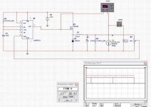
I thought I would post something that I just started to work on for your comments. please note that this is not meant to be correct or be actually built. It is at this stage just for discussion.
this is a 555-based smps. the 555 acts like a pulse width modulator (shamelessly stolen from National's datasheet on LM555, figure 8/9), control'd by a voltage signal on its pin 5. its output, pin 3, is attached to a mosfet Q1's gate. so Q1 will turn on and off based on pin 3. when Q1 is turned on, C2 gets charged via L1 (D1 is the free wheeling diode). R2 acts like a constant load, and variable current source, I1, acts like a variable load (in this case, at 6Khz). R3 samples the voltage across C2, and feeds it back to the 555's pin 5.
so by adjusting the wiper on R3, you get a desired voltage on C2.
R1/C1 is usual charge/discharge network for a 555 astable.
at this particular configuration, the output is rock solid, after the 50ms or so, at 7.738v. So it appears to work on paper.
Questions:
1) will it work in reality?
2) what can be done to make it better topology-wise? and why?
3) how to optimize parameter values?
Attachments
Congratulations, you have figured out by yourself the basic 'buck converter' topology with voltage contol [actually some kind of histeresis peak voltage control]
It may work in reality with some changes
Output filter is not realistic, you can´t use 47mH inductors with 0 ohm DC resistance nor 470uF capacitors with 0 ohms ESR [not to talk about the size and weight of a 47mH 2A inductor]
The output filter is nothing but a simple 2th order filter feed by a PWM signal that has AC and DC components. The filter should give good attenuation to AC components [whose minimum component is the switching frequency] and output the DC component 'clean'
So if you operate at 100Khz then your output filter should provide good attenuation [ie:60dB] at 100Khz and higher frequencies [you may add an aditional LC filter to smooth things further]
The output filter is placed in the 'transfer function' of the converter, so try to simulate 47mH and 470uF as a 2th filter with little or no load and you will see the huge resonance peak it causes
To be able to apply feedback in a reliable way to the whole thing, you have to design the filter to have little peaking and apply some degree of frequency compensation to the 'error amplifier' in order to prevent positive feedback [like in power amplifiers] [usually a zero near one of the output poles of the filter]
The way in wich the MOSFET is driven is also unrealistic, a consistent square wave between gate and source must be used
The control circuit is also unrealistic since it appears to work at a variable frequency and this makes it hard to filter the output, try to use a PWM whose duty cycle is controlled by an operational amplifier whose output is proportional to the difference between output voltage and desired output voltage [gain should be rolled off to avoid feedback at the switching frequency and above]
You should try to bread-board something with a SG3525 o TL494 [typical cheap control ICs], an iron powder inductor, proper mosfet drive
For that kind of converters, schottky diodes are recommended since they have negligible reverse recovery time, so you can swicth a MOSFET over the diode when it's conducting without causing very high current transients due to the diode apearing as a short-circuit for 100ns or so until it stops conducting [look at diode datasheets for reverse recovery waveforms and timing]
thanks eva, you raised a lot of good points and I don' thave all the answers.
the frequency of the 555 is determined by r1/c1.
Actually the circuitry has a foudamental flaw: it didn't have a trigger signal,.
it did work in my simulations but seems to suffer from low reaction time (with the trigger at 100khz). not sure why.
to have a consistant Vgs switching signal, I would have to use a p-channel mosfet. but then the phase of the 555 modulator is 180 degree out. so I wouldn't know how to make it work that way.
what I am really interested is to have a similar circuitry but works off line voltage.
I guess we aren't there yet.
the frequency of the 555 is determined by r1/c1.
Actually the circuitry has a foudamental flaw: it didn't have a trigger signal,
.it did work in my simulations but seems to suffer from low reaction time (with the trigger at 100khz). not sure why.
to have a consistant Vgs switching signal, I would have to use a p-channel mosfet. but then the phase of the 555 modulator is 180 degree out. so I wouldn't know how to make it work that way.
what I am really interested is to have a similar circuitry but works off line voltage.
I guess we aren't there yet.
- Status
- This old topic is closed. If you want to reopen this topic, contact a moderator using the "Report Post" button.
- Home
- Amplifiers
- Class D
- Line-powered SMPS for Power Amp?