That looks wonderful!
I had a thought: If there were vent holes in the bottom of the enclosure, located directly underneath all 3 boards, then cool air would voluntarily blow against the bottom sides of the boards.
Really good craftsmanship. Looks great.
I glue (with cyanoacrylate) a heatsink to the top of the chip housing. It leaves me more thermal margins. But, once on you won't get it off again.
Thank you both!
You reminded me I wanted to make a couple comments on thermals.
In the v1.1 complete amp pictured above, I let it run overnight in my basement, on 85dB, 6ish ohm speakers (Paul Carmody's Speedsters) at a volume loud enough that I can hear the music over my rowing machine. I didn't take SPL measurements, but that's about as loud as I ever go (and those speakers start "farting" pretty quickly anyway). Not concert levels by any means, but loud enough for me, with an admittedly modest volume preference. But, I pulled the case off and did the touch my finger to the chip temperature test. Not even warm. The heatsinks on the PSU weren't warm either. To be sure, I wasn't pushing much current through.
Obviously that's extremely imprecise, but for modest applications, I think this design should generally be cool enough without needing fancy measures.
The SO-32 version of the chip dissipates heat through the chip body, as well as the four pins at each corner of the chip (1, 16, 17, 32). I put a copper pour on the top of the board, around the tda8932 chip, extending outwards a bit, and stitched to the bottom copper layer with vias. I don't have the chops to do thermodynamic modeling, but my hope is that this is enough copper to keep the chip cool under most operating conditions. It has to be better than the tiny cheap Chinese boards, by simple virtue of having more copper, being a bigger board.
That said, as Daniel and FauxFrench pointed out, there are ways of further improving thermal performance: more case ventilation, and cementing a heatsink to the chip itself. Another option might be to add a silent (slow RPM) fan. Yet another option is to use a thermal pad to thermally mate the PCB to the enclosure (assuming the enclosure is metal). GMARSH advocated this for his "Wiener" tpa3118 amp. Granted that was a different chip, but the idea is that the chip heats up the PCB, and the thermal pad allows the PCB to dissipate heat onto the chassis. IIRC, he claimed he used this technique and was able to run a straight sine wave through the tpa3118 at a fairly high voltage without tripping the thermal protections.
Usually, that's from reducing/preventing non-audio workload. The means for running cooler is probably your more complete input filter and better power. Also the thicker inductors aren't heating as much. At least 3 different efficiency improvements are the likely means for it running cooler.. . . 85dB, 6ish ohm speakers. . . touch my finger to the chip temperature test. Not even warm. . .
Hi all.. I have 2 small ~20W russian power transformers originally intended for tube amp heating etc. but I follow a new design which needs more power (for heating) so they are unused now.
I thought I build a small Class-D amp with some cheap eBay modules for my sister in a dual monoblock design and after having calculated my voltage after rectification, these modules linked in the 1st post got a click yesterday and are just on their way to my home.")
Sadly I had no time yesterday to dig myself through all these (now) 61 pages in this topic. Could you recommend me some nice things as a design feature I should definitely take care of ?
- Configured my secondary windings these little boards would be driven by 21V DC after rectification. Does the PSU part need to be regulated or can remain a simple unregulated one ? (Graetz bridge and filtering, nothing else). I don't mind making it regulated and loosing some voltages or watts at the end.. it's a fun project to make use of the transformers, no big audiophile thing
- anything else, any tricks worth to consider/implement ?
For now I plan to build with "huge" electrolytics+film capacitors on the filtering side, linear PSU.. - but no voltage regulation planned yet. Should I .. ? Many thanks
I thought I build a small Class-D amp with some cheap eBay modules for my sister in a dual monoblock design and after having calculated my voltage after rectification, these modules linked in the 1st post got a click yesterday and are just on their way to my home.
Sadly I had no time yesterday to dig myself through all these (now) 61 pages in this topic. Could you recommend me some nice things as a design feature I should definitely take care of ?
- Configured my secondary windings these little boards would be driven by 21V DC after rectification. Does the PSU part need to be regulated or can remain a simple unregulated one ? (Graetz bridge and filtering, nothing else). I don't mind making it regulated and loosing some voltages or watts at the end.. it's a fun project to make use of the transformers, no big audiophile thing
- anything else, any tricks worth to consider/implement ?
For now I plan to build with "huge" electrolytics+film capacitors on the filtering side, linear PSU.. - but no voltage regulation planned yet. Should I .. ? Many thanks
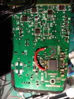
For the longest time I was trying to fix my 1st generation Creative Gigaworks T40, it is based off this TDA8932, they are like 10 years old.
At first I recapped it, some of the larger one were toast but it was still broken.
Replaced the opamps, one transistor (because it was running hot) then the main IC...still no go.
I almost gave up on and converted them as passives speakers but they sounded tiny when powered with a Breeze TPA3116, was about to salvage the capacitors until I gave it another go yesterday and strumbled upon this thread at Elektroda, appears to be a common occurence.
Turns out the leaked electrolytes damaged a trace/via, added a jumper wire and now it's back to life but with a caveat.
When first powered on, it appears to be muted for like a minute before I hear a pop followed by audio, any idea why? (something needing warming up or a cap that charges slowly?)
But once it's in that state, I can turn it on and off quickly and it will still play fine, unless I disconnect the PSU and wait, then the problem will come back.
I will start troubleshooting the mute pin 5 in case that cap is bad.
I did put it through a few heat gun cycles...might have damaged some passives...
Moral of the story, do not put vias directly underneath a eletrolytic capacitor if possible?
Last edited:
I think I found the problem, one of the capacitor takes forever to charge, a little 0805 L9 went missing, it's connected to pin 30 HPV1, followed by that slow charging 2200uF cap to another "L" and to the speaker.
I desoldered L10 for the other channel and measured 0.2ohm, is that an inductor? Ferrite bead? How to ID it?
The datasheet only shows a simplified schematic.
Edit: Found AN10436, is it part of the LP filter?
I desoldered L10 for the other channel and measured 0.2ohm, is that an inductor? Ferrite bead? How to ID it?
The datasheet only shows a simplified schematic.
Edit: Found AN10436, is it part of the LP filter?
Attachments
Last edited:
Bypassed and power on delay is gone, audio kicks in instantly, seems to work fine but maybe a bit harsher on the highs, could by my imagination, will try to replace the pot as it's a bit scratchy.
Came with linear B503 pots, ordered some Alpha log A50k pots instead.
Any input on the impact of bypassing these little guys on SQ?
Came with linear B503 pots, ordered some Alpha log A50k pots instead.
Any input on the impact of bypassing these little guys on SQ?
Hi all,
I have been experimenting with the TDA8932 sanwu board and wonder if anybody here can help me with a few issues.
I don't know if you people have noticed, but the board does not respect the original schematics and it's built with the input in SE and the output in BTL (the inputs are not paralleled, with the IN2's left unconnected, and the negative is connected to ground). I have modified the board so that it is configured as the original schematics, changed the input and output caps, and added better filtering caps for the supply. I have also added a 470uF cap to pin 12. With the mods the board sounded way better, even if more susceptible to noise with the Input negative off the ground.
My tests were going well until, without any apparent reason, the amp went mute (dead?). I must have done something wrong to cause a temporary (or permanent) fault, but no idea what. Has anybody here experienced this sort of thing? I have checked for shorts, resoldered a few things and nothing... Perhaps a static discharge damaging the amp?... Are these chips that delicate? I need to know what I might have done before embarking in new mods...
I would appreciate suggestions. Thanks!
The lack of replies suggest no-one has had this issue. Mine are still fine... and I received Matt's boards today (Thank you Matt!) so I'll be building some more soon
An externally hosted image should be here but it was not working when we last tested it.
An externally hosted image should be here but it was not working when we last tested it.
Last edited:
TDA8932 Blue Board Schematic
Hi
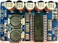
I have been following this thread for a while, and am also playing with one of the cheap TDA8932 blue boards (photo attached).
Whoever designed the boards did a horrible layout, but to start to figure out what exactly they did, I first reverse engineered the board and drew the schematic. (I started from the TDA8932 KiCad project that was posted earlier, but can't find it now to thank the author). The schematic is attached as pdf and as KiCad sch in the zip.
The resistor values in the schematic are correct, but I did not measure the caps to confirm their values, so for them I used the standard values.
As can be seen from the schematic, they took a few shortcuts and used the minimum number of components. Although they did connect a diode to POWERUP, which I believe is not necessary, and have not been able to figure out why...
So hopefully some of you find the schematic useful to improve and mod the cheap boards
Hi
I have been following this thread for a while, and am also playing with one of the cheap TDA8932 blue boards (photo attached).
Whoever designed the boards did a horrible layout, but to start to figure out what exactly they did, I first reverse engineered the board and drew the schematic. (I started from the TDA8932 KiCad project that was posted earlier, but can't find it now to thank the author). The schematic is attached as pdf and as KiCad sch in the zip.
The resistor values in the schematic are correct, but I did not measure the caps to confirm their values, so for them I used the standard values.
As can be seen from the schematic, they took a few shortcuts and used the minimum number of components. Although they did connect a diode to POWERUP, which I believe is not necessary, and have not been able to figure out why...
So hopefully some of you find the schematic useful to improve and mod the cheap boards
Attachments
I will be the first to thank you for this very useful schematic.
I notice a 10R resistor inserted between the general supply rail and the analog supply pin. Then we do not need to lift up the analog supply pin and insert 10R - we can go directly for adding a larger decoupling capacitor.
I am one of those really appreciating this mall board disregarding its obvious limits. It is "dirt cheap" and nevertheless sounds great. I know Matt has made a much better layout for this impressive chip.
Thanks, FF
Last edited:
hberner - are you sure about the wiring of the signal input? On my cheap little blue boards, the negative input is shorted to ground.
IMO, there is some ambiguity about this in the datasheet. diyAudio member Spartan brought it up to me in an email, can't remember if he posted about it in this thread. In the datasheet, look at Figure 7 on page 11: it shows the negative input shorted to ground (which doesn't make any sense to me).
I used Figure 37 on page 38 as the basis for my design; it does not have the cold input ground short.
In fact, that was one of the main drivers for creating my own board: to have working differential input.
Yes, although they don't make it clear, that's how to connect an unbalanced signal to the amp, and that's how the blue Sanwu boards are configured.look at Figure 7 on page 11: it shows the negative input shorted to ground
If you want to connect a balanced signal you just need to break that connection to GND.
That's what I did, but I went a step further and fed the centre-tap of my DAC's output transformer to pin 12 of the TDA8932 chip (thanks to abraxalito for this configuration tip). In my case there was no connection from audio source to the GND pin(s) of the TD8932 at all. But in all other situations with a balanced connection, you should connect your source's audio GND to TDA8932 GND.
You can read about my adventure with the TDA8932 here -
TA2020 vs TPA3118 vs TDA8932 comparison
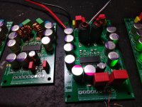
I've built up all six of Matt's boards in various configs. I've listened to three so far - two are identical config and sound identical so it seems the builds are fine. I was concerned about the chip soldering because the pads are short but it's fine after all. One sounds better - it has 10uH air core coils set for 4ohm speakers, C25 on Pin12 is a Ruby 1200uF 6.3v. For VPA, C24 and C14 are both solid poly 820uF after a 10R (perhaps to be replaced with a ferrite), and input coupling are 10uF Wima with 330pf pps film bypasses. The air core don't get hot so this amp likes them They come from an old Charlize II amp so they have double windings separated by EMS paper I believe, with a third winding that goes to ground as a shield. The amp sounds fabulous. Thanks Matt
They come from an old Charlize II amp so they have double windings separated by EMS paper I believe, with a third winding that goes to ground as a shield. The amp sounds fabulous. Thanks Matt Attachments
Last edited:
You can read about my adventure with the TDA8932 here -
TA2020 vs TPA3118 vs TDA8932 comparison
I'm still a fan of the TA2020 and the best is a Charlize II of the ones I've tried - I still listen to this amp all the time. I prefer the warmth of this to the clinical 3118/6. I also tried air core coils with 3116 and it overheated them so it's not on my "Best of Class D" album. Have you tried any of the TK2050 amps? Sure, HiFiMeDIY and a ton of others still sell them and they're still very popular too.
While comparing the Charlize2 to the Sanwu TPA3118 and TDA8932 boards, my one big discovery was that my DAC's unbalanced outputs are quite coloured, whereas the balanced outputs of the DAC are very good. (Excellent, in fact).I'm still a fan of the TA2020 and the best is a Charlize II of the ones I've tried - I still listen to this amp all the time.
And since the Charlize2 cannot accept a balanced signal, my listening tests then focused only on the 3118 and 8932.
So looking back, my listening tests were not really fair to the Charlize2 - because I only heard it as fed from a tone-heavy audio source.
I'm tied up for the next few weeks, but once I have half a day free I will make a point to re-test using a better unbalanced audio source. My old Denon DCD-690 CD player should be good enough for this. Stay tuned.
No. I was under the impression that the Sure amp with the biggest reputation for SQ (or hype factor) was the one with STA516BE + TC2001 chips - model AA-AB32313. Some say it beats the flavour-of-the-month TPA3255.Have you tried any of the TK2050 amps? Sure, HiFiMeDIY and a ton of others still sell them and they're still very popular too.
But I don't want/need these powerful beasts. To drive my MarkAudio A7.3 speakers I just want a low/mid power amp, and the one I'm about to build is the TPA3250 EVM board.
I was under the impression that the Sure amp with the biggest reputation for SQ (or hype factor) was the one with STA516BE + TC2001 chips - model AA-AB32313. Some say it beats the flavour-of-the-month TPA3255.
It is the TC controller that makes all these TC + amps special apparently - it's one of the very few class D that doesn't see distortion rise with frequency, which is why I think it's worth a listen if you get a chance. But then again, it'd probably be better to work on the SE output of the DAC first
I'm still a fan of the TA2020 and the best is a Charlize II of the ones I've tried - I still listen to this amp all the time. I prefer the warmth of this to the clinical 3118/6. I also tried air core coils with 3116 and it overheated them so it's not on my "Best of Class D" album. Have you tried any of the TK2050 amps? Sure, HiFiMeDIY and a ton of others still sell them and they're still very popular too.
I have a TK2050 amplifier (TC2001/STA505) and it sounds great. A problem is heating as the switching frequency (variable) extends beyond 500KHz.
- Home
- Amplifiers
- Class D
- Fasten seat belts. TDA8932 pessimistic review.