Now, take my "review" with a grain of salt. Compared to you eggheads ( and I mean that in an envious way  ) I'm at a low level of expertise here . You can show me the technical graphs and all of that, and I'll be asking if that is a good or bad graph. Distortion is a bad thing, right?
I probably have never heard high end equipment.
I have two of these for stereo use. I find the bass to be tight, and ample. I might even like the bass better than with the TPA3116. I need to compare them side by side. Vocals, and the high frequencies sound good to me. Two of these provide plenty of power for my use. I'd be quite happy with this board as my main amplifier
) I'm at a low level of expertise here . You can show me the technical graphs and all of that, and I'll be asking if that is a good or bad graph. Distortion is a bad thing, right? I probably have never heard high end equipment.
I have two of these for stereo use. I find the bass to be tight, and ample. I might even like the bass better than with the TPA3116. I need to compare them side by side. Vocals, and the high frequencies sound good to me. Two of these provide plenty of power for my use. I'd be quite happy with this board as my main amplifier
Last edited:
Charlie, I find it intensely valuable when someone disagrees with me. So, thank you!
Well, that is because doing better is always going to be a good thing, and it isn't really important if that is comfortable.
It is a fixed gain, with the setting internal to the chip. Can you suggest a reasonably safe way to add supplementary negative feedback?
Sir, I would measure if I could, but that has not been going well.
Again, I'd like to mention, for this particular amp, measurements are not so important unless we changed/altered/modded it. It and I (combined) can sort of self-measure at least that far, although not much farther (op-amps are usable as measuring equipment--that includes power-op-amps). This rather subjective success is because its flaw is extremely obvious, agrees with its datasheet and therefore high resolution is not mandatory at this time (unless we make a change to cause the need of verification).
Possibility of fail certainly does exist!
However I was looking for clues.
I found the clue that I wanted.
But, that was not expected.
Subjectively, I can determine: A (excellent), C (passable) and F (fail), but precision accurate percentages and graphs are not currently available by that method. Thanks to the chip working right on practically as described by its datasheet, my review was not any more (nor less) valuable than a really colorful translation of that datasheet, except. . . the sole difference is that I named some applications it would be good for and some that it won't do well--if TV is your love, then don't buy this amp.
The typical late 70's, early 80's STK production amplifier has far too much gain, which is to assure stability in ALL conditions, via outright placidity overdo. Normally I love high gain because when I buy an amplifier, I probably DID want amplification. So, I'd be the last person to complain about that. But, I did. It has too much gain. Datasheet power noise rejection chart with typical rising response confirms my claim (mostly, but not entirely--they were not quite that informative).
100uF (small size) decoupling (even if array style), and still manage to depress the voice band so you don't need an eq nor baxandall? I did check the power circuit for known causes and filtering. None present! It does NOT have a powerside circuit that could cause a loudness contour. This amp is overcomp via simple gain comp--too much! No. NXP basically gave it a xanax to make a VERY stable production amp with a pretty tone. That is my claim, which doesn't conflict the datasheet.
Thanks to member abraxalito, I bought this amp, even though the datasheet's figures could mean either a sonic weapon (which one would expect of a flawed class d amp from ebay) OR a xanax toting classic miraculously presented in class d form (which is true, so far as I know).
I got it for "especially inoffensive" background music for my office. Its flaw has provided the means for that application to succeed without an eq. Sure, I could have used a Technics SA-80 (STK), but those are more expensive, considerably larger and slightly less energy efficient. The older part just won't fit peaceably inside my speaker enclosure. So, I claim that the newer part can do the job, but only because it IS doing the job.
I wanted to lambast this class d whippersnapper; however, it is merely more important to tell the truth: It is overly compromised for pleasant placidity, at some expense, and will do very well for inoffensive background music replay, at the cost of doing poorly at movie soundtracks. This claim is partially supported by the datasheet, with the extent depending on power circuit, of course.
So, I'm absolutely certain, that you can justifiably complain about a lack of information. But, have you found an error??? Did your real physical sample do anything different than I said it would do???
Meanwhile, the path forward is reducing the gain somehow. Otherwise, just use the datasheet.
Well, that is because doing better is always going to be a good thing, and it isn't really important if that is comfortable.
Charlie, an important change is needed, and that is LOWER GAIN. Given the practically proofed datasheet, it couldn't be necessary to measure the amp unless we change it (measuring is important afterwards, for quality control). But, we do need to change it, and that will also cause the need of measuring it. According to the 36db datasheet figure, the power noise rejection datasheet graph AND my subjective bit, the gain is harmfully too high.Now on the other hand if you start off with SOME MEASUREMENTS and then proceeded to give your "feelings" along with it, that would be a different matter altogether. But it seems that you never do that, Daniel.
It is a fixed gain, with the setting internal to the chip. Can you suggest a reasonably safe way to add supplementary negative feedback?
My meager signal measuring equipment is currently broken due to computer upgrades. I don't think that it will measure anything important over its self-noise. I claim that my rather experienced ears are probably not worse than really broken measuring equipment. Do you think such claim is reasonable? OH, I'm still irked that the cheap stuff didn't have a "zero out" functionality, but instead simply assumed that itself was perfect. Well, I claim that it wasn't ever perfect, but even 10 times off the mark was still useful. That's when it was new. Its a LOT worse now! Currently, I'm a little confused about how to proceed to reacquire measuring capacity. I do have need of measuring audio proportion and I do have need of measuring frequencies just above the audio band which can still affect an ear and/or hetrodyne with audio frequences. Any clues on a replacement something non-bank-busting and straightforward to operate?I'm very disappointed in what seems to be a very typical style for you when you post a "review" about some part or circuit: NO MEASUREMENTS!
Sir, I would measure if I could, but that has not been going well.
Again, I'd like to mention, for this particular amp, measurements are not so important unless we changed/altered/modded it. It and I (combined) can sort of self-measure at least that far, although not much farther (op-amps are usable as measuring equipment--that includes power-op-amps). This rather subjective success is because its flaw is extremely obvious, agrees with its datasheet and therefore high resolution is not mandatory at this time (unless we make a change to cause the need of verification).
According to the datasheet, it won't be shouty, and bad power could make it go dull. I mentioned a difficult to reproduce xylophone like signal and a voice band signal as well. By ear, my accuracy on detection is insignificant, with no useful proportions resulting from judgement of same (as normal for human ears); however, my accuracy on comparison is 0.03db (via measuring equipment that may be off by 10x either way). Bear in mind that the amplifier gain is 36db, and therefore the judgements may be close to adequate. That all depends on how the information was used.All you seem to be capable of is prose about the item in question, using words like "shouty" or "dull" or saying it sounds like "a 70's amp". What crap. Words are a dime a dozen, and "words" are what snake oil salesman use to convince people about some quality of their product that just cannot be captured by any measurement.. . . Qualitative "feelings" in which you talk about "tinkly" notes (that's a direct quote from above) are really not worth the electrons used to render them.. . .
Possibility of fail certainly does exist!
However I was looking for clues.
I found the clue that I wanted.
But, that was not expected.
Subjectively, I can determine: A (excellent), C (passable) and F (fail), but precision accurate percentages and graphs are not currently available by that method. Thanks to the chip working right on practically as described by its datasheet, my review was not any more (nor less) valuable than a really colorful translation of that datasheet, except. . . the sole difference is that I named some applications it would be good for and some that it won't do well--if TV is your love, then don't buy this amp.
The typical late 70's, early 80's STK production amplifier has far too much gain, which is to assure stability in ALL conditions, via outright placidity overdo. Normally I love high gain because when I buy an amplifier, I probably DID want amplification. So, I'd be the last person to complain about that. But, I did. It has too much gain. Datasheet power noise rejection chart with typical rising response confirms my claim (mostly, but not entirely--they were not quite that informative).
100uF (small size) decoupling (even if array style), and still manage to depress the voice band so you don't need an eq nor baxandall? I did check the power circuit for known causes and filtering. None present! It does NOT have a powerside circuit that could cause a loudness contour. This amp is overcomp via simple gain comp--too much! No. NXP basically gave it a xanax to make a VERY stable production amp with a pretty tone. That is my claim, which doesn't conflict the datasheet.
Thanks to member abraxalito, I bought this amp, even though the datasheet's figures could mean either a sonic weapon (which one would expect of a flawed class d amp from ebay) OR a xanax toting classic miraculously presented in class d form (which is true, so far as I know).
I got it for "especially inoffensive" background music for my office. Its flaw has provided the means for that application to succeed without an eq. Sure, I could have used a Technics SA-80 (STK), but those are more expensive, considerably larger and slightly less energy efficient. The older part just won't fit peaceably inside my speaker enclosure. So, I claim that the newer part can do the job, but only because it IS doing the job.
I wanted to lambast this class d whippersnapper; however, it is merely more important to tell the truth: It is overly compromised for pleasant placidity, at some expense, and will do very well for inoffensive background music replay, at the cost of doing poorly at movie soundtracks. This claim is partially supported by the datasheet, with the extent depending on power circuit, of course.
So, I'm absolutely certain, that you can justifiably complain about a lack of information. But, have you found an error??? Did your real physical sample do anything different than I said it would do???
Meanwhile, the path forward is reducing the gain somehow. Otherwise, just use the datasheet.
For the TDA8932, you'd want more negative feedback. For the TPA3116 you'd want to run parallel or PBTL mode.Now, take my "review" with a grain of salt. Compared to you eggheads (and I mean that in an envious way
I have two of these for stereo use. I find the bass to be tight, and ample. I might even like the bass better than with the TPA3116. I need to compare them side by side. Vocals, and the high frequencies sound good to me. Two of these provide plenty of power for my use. I'd be quite happy with this board as my main amplifier
Distortion is a bad thing when in case there's a lower distortion way to get the same job done. For example, the higher distortion of an EQ is a bad substitute for the lower distortion of a padded midrange or bsc like circuit in the speaker.Distortion is a bad thing, right?
For the TDA8932, you'd want more negative feedback. For the TPA3116 you'd want to run parallel or PBTL mode.
Distortion is a bad thing when in case there's a lower distortion way to get the same job done. For example, the higher distortion of an EQ is a bad substitute for the lower distortion of a padded midrange or bsc like circuit in the speaker.
I was joking about distortion, I know it's bad. What I don't know is what this means , "For the TDA8932, you'd want more negative feedback. For the TPA3116 you'd want to run parallel or PBTL mode."
Well, adding supplementary negative feedback to the TDA8932 is theoretically possible, would lower the gain and reduce distortion.I was joking about distortion, I know it's bad. What I don't know is what this means , "For the TDA8932, you'd want more negative feedback. For the TPA3116 you'd want to run parallel or PBTL mode."
Or, with the TPA3116, you wanted greater output linearity so you could get some better bass, and the most popular way to do that for little amp chips, is paralleling. I guess that this TPA3116 "dual chip" is a PBTL board: 2 100W TPA3116 D2 Dual Channel Digital Audio Amplifier Board 12V 24V for Arduino | eBay Ebay# 400930718344
The microAmp!
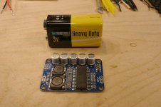
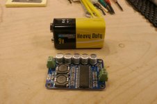
My amp boards arrived today. This thing is stupidly small. It's the microAmp! Here are couple of pics with a 9V battery for some perspective. I was expecting something a little bigger. The little green connectors work great, but be careful on the speaker-out. You need a little strip of insulting material over two SMD caps/resistors that the connector will rest on. Otherwise you run the risk of shorting them out. Not good. Amazing sound from such a tiny device. Cool.
My amp boards arrived today. This thing is stupidly small. It's the microAmp! Here are couple of pics with a 9V battery for some perspective. I was expecting something a little bigger. The little green connectors work great, but be careful on the speaker-out. You need a little strip of insulting material over two SMD caps/resistors that the connector will rest on. Otherwise you run the risk of shorting them out. Not good. Amazing sound from such a tiny device. Cool.
Attachments
My amp boards arrived today. This thing is stupidly small. It's the microAmp! Here are couple of pics with a 9V battery for some perspective. I was expecting something a little bigger. The little green connectors work great, but be careful on the speaker-out. You need a little strip of insulting material over two SMD caps/resistors that the connector will rest on. Otherwise you run the risk of shorting them out. Not good. Amazing sound from such a tiny device. Cool.
I really like the sound myself. Two of them give me plenty of volume.
I recieved mine and i have to say that i'm really impressed with what i got for less than 6€.
The strong bass is very audible.
When i first listened to the amp i had to check the eq.... but no extra boost was set.
The amp gets quite warm and so do the inductors.
In my experience the class d amps with small inductors (like the cheap blue TDA7492 or the sure TPA3116) get hotter than others.
The strong bass is very audible.
When i first listened to the amp i had to check the eq.... but no extra boost was set.
The amp gets quite warm and so do the inductors.
In my experience the class d amps with small inductors (like the cheap blue TDA7492 or the sure TPA3116) get hotter than others.
My amp boards arrived today. This thing is stupidly small. It's the microAmp! Here are couple of pics with a 9V battery for some perspective. I was expecting something a little bigger. The little green connectors work great, but be careful on the speaker-out. You need a little strip of insulting material over two SMD caps/resistors that the connector will rest on. Otherwise you run the risk of shorting them out. Not good. Amazing sound from such a tiny device. Cool.
thanks for the pics. I've bought those green things before but I don't know exactly what they're called. Screw terminals? I don't know. I need to buy some more, know of a good seller? Or what keywords I should use to search? Thanks in advance.
Also- are you going to use separate power supplies as recommended earlier in the thread? Seems like that would significantly raise the cost of a stereo project. And did you go with 19v?
You made my day!You need a little strip of insulting material
thanks for the pics. I've bought those green things before but I don't know exactly what they're called. Screw terminals? I don't know. I need to buy some more, know of a good seller? Or what keywords I should use to search? Thanks in advance.
If you like genuine stuff, have a look for:
https://www.phoenixcontact.com
1 supply with 2 schottky is cheaper.Also, are you going to use separate power supplies as recommended earlier in the thread? Seems like that would significantly raise the cost of a stereo project. And did you go with 19v?
left v+ <- 19vdc -> right v+
The diodes (shown ->) are serving as a "Y" splitter.
They'll work best if situated as close to the amplifier board as possible (on the amplifier board if possible).
MBR1645 works good, and is very efficient.
MUR can also be used as can almost any diodes rated at least 3a, like 1n5405.
P.S.
If this is odd looking, just remember it is more common to see it done with linear regulator chips, at some difference in cost.
Last edited:
i use these connectors.
Serie 2500 2.54mm - Wafer & Housing & Crimp Terminal - Connectors & Sockets
They are ultra low cost, but fit my needs (especially force me to use right polarity).
Serie 2500 2.54mm - Wafer & Housing & Crimp Terminal - Connectors & Sockets
They are ultra low cost, but fit my needs (especially force me to use right polarity).
Arghh my long response disappeared. Token expired, eh?
I will try to type it again, but shorter.
Thanks for the replies.
I guess the terminals I was looking for are simply called screw block terminals. I have some crap molex knock off wafer terminals and housings and they are definitely inferior. So are the crimp terminals.
My project was going to use a single power supply for a pair of small monitors, each using a mono amp. This amp looks like a good candidate. I had planned on putting the PS in one speaker. I was going to make a custom 4 pin cable with power and shielded signal, or two cables if there was interference.
I guess that isn't a good idea if the diode needs to be very close to the amp boards, and simply sharing the power will cause problems too. I hadn't expected this, because I'm very much not an EE.
Is there another option?
Thanks
One diode for each amp board would be normal, so that's 2 for stereo, also quite normal in automotive applications. Main use is decreased power noise. Anyway, that doesn't really complicate your plans, does it? If so, you can omit, but your layout wouldn't be different at all.. . .if the diode needs to be very close to the amp boards. . .
For this amp, 1 per each channel. For a 2-channel amp, the approach looks just like a "Y" adapter. That will prevent some crosstalk interference (at the power circuit), with results similar to dual mono, but a much smaller price.oh I see. I can use two. ha! great, I'll read more about these diodes and get a couple, or four.
Option: You could substitute linear regulator chips (still 1 per each channel). That's actually the normal way to do it, but does cost a little more.
1 supply with 2 schottky is cheaper.
left v+ <- 19vdc -> right v+
The diodes (shown ->) are serving as a "Y" splitter.
They'll work best if situated as close to the amplifier board as possible (on the amplifier board if possible).
MBR1645 works good, and is very efficient.
MUR can also be used as can almost any diodes rated at least 3a, like 1n5405.
P.S.
If this is odd looking, just remember it is more common to see it done with linear regulator chips, at some difference in cost.
If I understand this correctly, pin 1 on the diode connects to the V+ on the board and the Pin 2s form the "Y" and connect to the 19VDC. Right?
Now for 3.10€/board
Livraison gratuite! Amplificateur de puissance numrique conseil module 35 w mono amplificateur module haute puissance TDA8932 faible consommation d'nergie dans Autres composants lectriques de Fournitures et composants lectroniques sur AliExpr
or 3.99 $ here :
http://www.ebay.com/itm/Digital-Amp...998218?hash=item33abe140ca:g:RqEAAOSwAYtWMwW7
Thanks for your thread
Last edited:
- Home
- Amplifiers
- Class D
- Fasten seat belts. TDA8932 pessimistic review.