In this experiment...
The tweeter is connected from one of the outputs, then returned with 4u7~10u cap series to power ground, for SE mode.
The optional midrange is connected from the opposite output, then returned with 22u~47u cap series to power ground, for SE mode.
The woofer is connected between both of the outputs (normal hookup) for BTL mode.
...............................................
I'm so astonished.
This post is the "easy-solder" method to get hi-fi out of this amp.
Thanks for this - I'm doing it for a BT omni-directional speaker and it does indeed work well. Plus I've discovered another virtue of this amp - over 90% efficiency makes it the best choice I've found for battery amps.
An externally hosted image should be here but it was not working when we last tested it.
Just got a new board that has SANWU on it and it's much better quality, even the parts are different. the first one I have doesn't have SANWU on it and even the TDA8932 is different. This one is much quieter and the Bluetooth female voice is at very low volume. Very pleased with it. The Bluetooth chip on old one had the Windows driver from 2010, the new board has Bluetooth chip with Windows driver from 2017.
Attachments
Last edited:
The Bluetooth chip on old one had the Windows driver from 2010, the new board has Bluetooth chip with Windows driver from 2017.
Windows driver? What do you mean with 'windows driver'?
When you pair the Bluetooth amplifier with a Windows PC, you can check what drive was installed for this. So the SANWU board has a newer version of it than the one without a label on it which looks fake.Windows driver? What do you mean with 'windows driver'?
When you pair the Bluetooth amplifier with a Windows PC, you can check what drive was installed for this. So the SANWU board has a newer version of it than the one without a label on it which looks fake.
Thank you for the explanation. I haven't done much with Bluetooth so far. The newer board probably got a newer Bluetooth version (which most likely sound better) and therefore Windows uses the newer driver or the driver simply got meanwhile an update (i.e. because of the BlueBorne security hole) but the amplifier board does, in fact, not have any Windows driver.
Connection and buzz
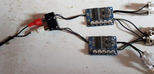
I received my boards and made the connections. Unfortunately the housing of one of the chokes is damaged but it doesn't fail. The boards already give a suprisingly good sound, but there is some noise and buzz. I currently use a 12V battery and tried a laptop power supply but that increased the buzz. Do I have a loose wire problem or can modding help to solve this?
I received my boards and made the connections. Unfortunately the housing of one of the chokes is damaged but it doesn't fail. The boards already give a suprisingly good sound, but there is some noise and buzz. I currently use a 12V battery and tried a laptop power supply but that increased the buzz. Do I have a loose wire problem or can modding help to solve this?
Attachments
The "buzz" is likely to be 50Hz or 100Hz (rectified) hum? Two reasons I can imagine for this are non-shielded wire between the input connectors and the amplifier input terminals in combination with a rather high impedance source, and moderate decoupling of the power supply lines.
As source, try with the headphone output of your smart-phone.
For the power supply decoupling, try to give the amplifiers some 2200uF decoupling each near the supply terminals of the amplifier. Now, you only have 500uF (5x100uF) and that is too little.
I have tried 6 of these boards without any hiss or hum you would notice.
The output filter coils are not designed to match the potential of the chip. They will probably saturate around 2 A (peak). This is how they can sell the modules so cheap.
The sound I have heard from these modules, modified with a better output filter, is really amazing for the price. 0.007% THD for the BTL coupling!
Last edited:
Thanks for your suggestions. The buzz can't be 50/100 hz mains as the amplifiers are fed by an 12V battery and the buzz and hiss are audible then too. It might come from the source (RPI with Asus Xonar U7 soundcard), but I don't have problems using this with most amplifiers. Only my 3116's have a comparable problem. When I disconnect the amplifiers from the source the buzz is very strong (still with battery)The "buzz" is likely to be 50Hz or 100Hz (rectified) hum? Two reasons I can imagine for this are non-shielded wire between the input connectors and the amplifier input terminals in combination with a rather high impedance source, and moderate decoupling of the power supply lines.
As source, try with the headphone output of your smart-phone.
For the power supply decoupling, try to give the amplifiers some 2200uF decoupling each near the supply terminals of the amplifier. Now, you only have 500uF (5x100uF) and that is too little.
I have tried 6 of these boards without any hiss or hum you would notice.
The output filter coils are not designed to match the potential of the chip. They will probably saturate around 2 A (peak). This is how they can sell the modules so cheap.
The sound I have heard from these modules, modified with a better output filter, is really amazing for the price. 0.007% THD for the BTL coupling!
Is decoupling with capacitors needed when a 12V battery is used?
The sound is so good that I'm thinking of using these amplifiers to do the tweeter section of an active 3-way using a DSP. Then the chokes are not the problem, but the buzz must be solved.
It can be 50/100 Hz being radiated to a high impedance input, even when operated from a battery. Try to connect two 1K resistors (and no soundcard) at the inputs until the buzz problem is solved. Is the buzz then gone?
Batteries are reasonably low impedance at low frequencies but not necessarily at higher frequencies. You can rely on good capacitors for the decoupling, not a battery.
Did operation from your smartphone help or was it the same?
Batteries are reasonably low impedance at low frequencies but not necessarily at higher frequencies. You can rely on good capacitors for the decoupling, not a battery.
Did operation from your smartphone help or was it the same?
Last edited:
Operation from smartphone stopped the buzz, even when I use the laptop power supply. But I need the Xonar for my DSP. I will try the 1 kohm suggestion. How do I connect this, between the + of the input and the amplifier?It can be 50/100 Hz being radiated to a high impedance input, even when operated from a battery. Try to connect two 1K resistors (and no soundcard) at the inputs until the buzz problem is solved. Is the buzz then gone?
Batteries are reasonably low impedance at low frequencies but not necessarily at higher frequencies. You can rely on good capacitors for the decoupling, not a battery.
Did operation from your smartphone help or was it the same?
No buzz with a smart-phone means that the amplifier is working well. You have a grounding problem. A smart-phone is always an intelligent first test because it is battery operated ("floating" potential wise) and has a low output impedance (designed for headphones).
First suggestion: could it be that you have turned the input wires around such that what is ground on your sound card is going to the amplifier inputs ("+") and the output lines from the sound card are going to ground ("-") on the amplifier boards? If so, it will leave some sound but with a lot of buzz.
Actually, from the photo you posted it seems to be wrong. I cannot see the connections inside the female connector but my guess is that the fully black wires are signal and the black/white wires are ground. You seem to have connected the black wires to amplifier ground ("-") and the black/white to signal inputs ("+"). Please check!
If there is no mistake in how the input wires are connected, please let me know and I will explain in a following posting how to lower the signal line impedance.
Last edited:
I checked it: the center of the RCA plug is connected to the + pole. The Xonar is a good quality soundcard but the impedance seems not so easy. Soms headphones have problems too. I really appreciate tour help.No buzz with a smart-phone means that the amplifier is working well. You have a grounding problem. A smart-phone is always an intelligent first test because it is battery operated ("floating" potential wise) and has a low output impedance (designed for headphones).
First suggestion: could it be that you have turned the input wires around such that what is ground on your sound card is going to the amplifier inputs ("+") and the output lines from the sound card are going to ground ("-") on the amplifier boards? If so, it will leave some sound but with a lot of buzz.
Actually, from the photo you posted it seems to be wrong. I cannot see the connections inside the female connector but my guess is that the fully black wires are signal and the black/white wires are ground. You seem to have connected the black wires to amplifier ground ("-") and the black/white to signal inputs ("+"). Please check!
If there is no mistake in how the input wires are connected, please let me know and I will explain in a following posting how to lower the signal line impedance.
The Sonar U7 has got a line-out (RCAs) and headphone out (jack). Use the headphone output because it is low impedance.
The idea with the 1K resistors is simple: load the source (the headphone output) with a load where it performs well and keep the input of the amplifier low impedance so it is little sensitive to radiated noise.
The two 1K resistors go between the "+" input terminal and the "-" input terminal. Try with both battery and power adapter.
The Sonar U7 has got a line-out (RCAs) and headphone out (jack). Use the headphone output because it is low impedance.
The idea with the 1K resistors is simple: load the source (the headphone output) with a load where it performs well and keep the input of the amplifier low impedance so it is little sensitive to radiated noise.
The two 1K resistors go between the "+" input terminal and the "-" input terminal. Try with both battery and power adapter.
I tried different values of resistors between 2K and 360 ohm. With lower levels the buzz decreased but unfortunately the efficiency lowered too. I had three other findings:
1. Connected devices to the RPI that control the Xonar are bad for noise, especially the monitor.
2. The speaker that I currently use (Tangband W8-1772) has extremely much detail. With other speakers the noise is less audible
3. I tested different outputs of the Xonar (RCA and other) but there is no difference in noise.
One easy conclusion: you have nice speakers with the Tangband W8-1772.
Then, to the more difficult:
The Sonar U7 has got no optical input such that it cannot be separated from the PC power supply in a simple manner.
An “RPI”, is that a USB hub?
I get the impression that you use a stationary ATX-type PC? The power supplies for those are designed to be powerful and cheap – not delicate with noise.
As your occupation is data scientist, I guess you have a laptop with you. Could you please try to run the Sonar U7 directly from a USB connector of that laptop? First with the laptop running on batteries, then with a power adapter.
If that works without buzz, can the laptop be a solution?
Today I re-connected my TDA8932 board (two of the same modules you have). The input to the amplifier is from an FX Audio DAC-X6, via a 25dB damping element (I have too much gain in the system). The amplifier is supplied from a 16V power adapter. Actually, for a start I also had some buzz because I had turned the 25dB damping element wrong. With this mistake corrected, only very little buzz remained when the sound was turned down and I put my head in front of the speakers. Very little, but still something. I do not recall such buzz from use of my Argon headphone amplifier instead of the DAC-X6 integrated headphone amplifier.
If you also have too much gain in the system, could such a damping element be a solution? It corresponds to only 10 Ohm across the amplifier input terminals.
If your PC has got an integrated sound-card, do you also have buzz when using that internal sound-card?
A more radical solution could be a signal transformer galvanic separating the amplifier input from the computer supply. It requires quite some work.
Please try the above experiments.
Last edited:
I received my boards and made the connections. Unfortunately the housing of one of the chokes is damaged but it doesn't fail. The boards already give a suprisingly good sound, but there is some noise and buzz. I currently use a 12V battery and tried a laptop power supply but that increased the buzz. Do I have a loose wire problem or can modding help to solve this?
That 'housing' is a vital part of the choke, the ferrite increases the inductance by a big margin. The choke loses a lot of its inductance if it isn't intact anymore. To make matters worse, it's a bridged amplifier and with different inductances each of the bridged channels works kinda against each other. You'll likely lose power and the amp will heat up much faster, but it will also result in a different behaviour since the output filter, that means it will sound different than the other board. It can also lead to distortion or noise, depending on the amp. That might be the source of your 'buzz' and it's easy to verify, disconnect the one board with the damaged ferrite core. If it's gone and comes back if you switch the boards, you found the culprit.
In any case, you should get a replacement board. I've ordered several times but last time I got also a board with damaged chokes on the last parcel, I had to replace the chokes and bought reluctantly ones which were more than the complete board because I couldn't wait for a replacement from china.
One easy conclusion: you have nice speakers with the Tangband W8-1772.
Then, to the more difficult:
The Sonar U7 has got no optical input such that it cannot be separated from the PC power supply in a simple manner.
An “RPI”, is that a USB hub?
I get the impression that you use a stationary ATX-type PC? The power supplies for those are designed to be powerful and cheap – not delicate with noise.
As your occupation is data scientist, I guess you have a laptop with you. Could you please try to run the Sonar U7 directly from a USB connector of that laptop? First with the laptop running on batteries, then with a power adapter.
If that works without buzz, can the laptop be a solution?
Today I re-connected my TDA8932 board (two of the same modules you have). The input to the amplifier is from an FX Audio DAC-X6, via a 25dB damping element (I have too much gain in the system). The amplifier is supplied from a 16V power adapter. Actually, for a start I also had some buzz because I had turned the 25dB damping element wrong. With this mistake corrected, only very little buzz remained when the sound was turned down and I put my head in front of the speakers. Very little, but still something. I do not recall such buzz from use of my Argon headphone amplifier instead of the DAC-X6 integrated headphone amplifier.
If you also have too much gain in the system, could such a damping element be a solution? It corresponds to only 10 Ohm across the amplifier input terminals.
If your PC has got an integrated sound-card, do you also have buzz when using that internal sound-card?
A more radical solution could be a signal transformer galvanic separating the amplifier input from the computer supply. It requires quite some work.
Please try the above experiments.
A RPI is a Raspberry PI Micro computer. My source is based on this tutorial Digital Crossover/EQ with Open-Source Software: HOWTO | Richard's Stuff with Music Player Daemon and Spotifyd Daemon installed. As the DSP in this solution is the crossover and corrects the speakers (even the Tangband needs linearization) using other sources like laptops and smartphones is not useful with the exception of testing things. A RPI is known as a very good source for music so I don't suspect it of buzzing. I have two RPI's and Xonar's and when I exchange them they behave the same. But I have to avoid connecting additional devices that creates noise. The TDA8932's play quite loud compared to other amplifiers so probably correcting the gain is something I should do, although the soundquality besides the buzz already is extremely well.
That 'housing' is a vital part of the choke, the ferrite increases the inductance by a big margin. The choke loses a lot of its inductance if it isn't intact anymore. To make matters worse, it's a bridged amplifier and with different inductances each of the bridged channels works kinda against each other. You'll likely lose power and the amp will heat up much faster, but it will also result in a different behaviour since the output filter, that means it will sound different than the other board. It can also lead to distortion or noise, depending on the amp. That might be the source of your 'buzz' and it's easy to verify, disconnect the one board with the damaged ferrite core. If it's gone and comes back if you switch the boards, you found the culprit.
In any case, you should get a replacement board. I've ordered several times but last time I got also a board with damaged chokes on the last parcel, I had to replace the chokes and bought reluctantly ones which were more than the complete board because I couldn't wait for a replacement from china.
Thanks for your thoughts. I used to expect that the value of the choke was determined by the core, not by the housing. Anyway, I planned to replace the chokes by bigger ones. Besides there is no difference in buzz between the amplifier with the damaged choke and the one with normal chokes. Even the soundquality is very well.
I still suggest you to try operating the Sonar from a laptop (battery/adapter) because we need to see if it is the RPI power supply that causes the buzz.
For damping element I suggest two 100 Ohm resistors (from the headphone outputs) going to two 10 Ohm resistors being grounded in the other end and then using the midpoints as input to the amplifier. It forms simple voltage dividers with 100+10 Ohm input impedance and 10 Ohm output impedance. Around 20dB damping.
For damping element I suggest two 100 Ohm resistors (from the headphone outputs) going to two 10 Ohm resistors being grounded in the other end and then using the midpoints as input to the amplifier. It forms simple voltage dividers with 100+10 Ohm input impedance and 10 Ohm output impedance. Around 20dB damping.
Thanks for your thoughts. I used to expect that the value of the choke was determined by the core, not by the housing.
There is no separate housing, that's the same material and part of the choke. It's the same as on a transformer, just because the metal is inside as well as outside of the coils does not mean it's not 'working'. If it was that case you can be 100% sure they would have saved the material or used something cheaper (i.e. plastic).
Ferrite core - Wikipedia
Magnetic core - Wikipedia
Besides there is no difference in buzz between the amplifier with the damaged choke and the one with normal chokes. Even the soundquality is very well.
If you have buzz on both then it's either a grounding problem or you've got stray high frequency interference. A shielded enclosure would be a solution for the latter, and looking at your amps, even shielded (coax) audio signal input cables could probably be a big improvement.
I have a Raspberry PI3 and that one is supplied from a rather moderate 5V supply (as recommended). That must mean, that little current is available for the USB outputs.
You supply your Sonar U7 from the RPI USB connector, thus, from the same power supply as for the micro-computer, am I wrong?
The Sonar U7 has got high performance circuits inside, including a headphone amplifier. That requires quite some current. Could it be that the Sonar U7 is simply starved from current and performs marginally (the buzz'ing) because of that?
Two ways to check: with a laptop or with a USB hub having its own 5V supply. If so, the USB hub with own supply may be a solution because the RPI supply is relieved from the Sonar U7 as load.
Last edited:
- Home
- Amplifiers
- Class D
- Fasten seat belts. TDA8932 pessimistic review.