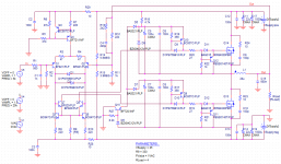
I've been doing some spice simulations on de Philips UcD amplifier, using the schematic of the UM10155 application note. Most of the results are identical to what I can find in other threads but I haven't been able to get the THD any lower than 0.3% while it it specified as lower than 0.03%. This specification is set at 10 W output power and I haven't been very succesful in determining the output power in the simulation. If I plot the rms power of the load about 27 W is dissipated, in the coil over a 100 W and in the two mosfets about 40W each. That doesn't seem right.
I've used a 5kHz 1v sinusoidail input, +/- 45Vdc supply and a 4 ohm load.
I've used a 5kHz 1v sinusoidail input, +/- 45Vdc supply and a 4 ohm load.
Attachments
@pbeckers
If you say the FETs dissipate that much then either the driving is not correctly done or the models for the FETs are wrong/bad (which is what I suspect). Besides these there may be other options to set in order to get desired accuracy (I don't know PSpice well enough to help you there).
@ionutzxpo
The results you tell about are impressing. Do you think you can you post a schematic or give some examples to the OP to help him?
I use LTspice so I don't know if the models are the same across simulators, or even if they benefit from the same calculations under the hood (to my knowledge, not quite), but I know that for a good FFT and .FOUR analysis data compression must be disabled and the timestep must also be lowered accordingly. If you have already did these and still get ugly numbers then I can only think of a bad model somewhere in there (the schematic seems fine).
You say you have seen other schematics. Have you tried running them and comparing the results? Even if it's not PSpice, they should be SPICE, so similarities must exist.
You say you have seen other schematics. Have you tried running them and comparing the results? Even if it's not PSpice, they should be SPICE, so similarities must exist.
In this thread a simulation was done in LT:
UcD Philips UM10155 LTspice simulation
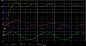
As you can see with similar results in distortion. My guess is it is due to startup effects, it takes a few cycles before the oscillator is at full amplitude. Would there be a way to start the fourier analysis with a delay?
As for the power dissipation in the parts other than the load, I'm also showing that when I provide a 0.001 vac input. The coil still dissipates over twenty watts and the two fets combined over ten watts. I've modelled the output filter with an ideal coil, how can it dissipate energy at all?
UcD Philips UM10155 LTspice simulation
As you can see with similar results in distortion. My guess is it is due to startup effects, it takes a few cycles before the oscillator is at full amplitude. Would there be a way to start the fourier analysis with a delay?
As for the power dissipation in the parts other than the load, I'm also showing that when I provide a 0.001 vac input. The coil still dissipates over twenty watts and the two fets combined over ten watts. I've modelled the output filter with an ideal coil, how can it dissipate energy at all?
@pbeckers
If you read these forums better you will find GOLD! ONLY if you read.
@bubulescu
If you read these forums better you will find GOLD! ONLY if you read.
example:http://www.diyaudio.com/forums/class-d/236703-ucd-philips-um10155-ltspice-simulation.html from start to end") in special PAGE 3
in special PAGE 3
If you read these forums better you will find GOLD! ONLY if you read.
@bubulescu
If you read these forums better you will find GOLD! ONLY if you read.
example:http://www.diyaudio.com/forums/class-d/236703-ucd-philips-um10155-ltspice-simulation.html from start to end
in special PAGE 3 @pbeckers
When you say "as you can see" are you referring to the way the waveforms *look* like or how the measured results look like? I cannot make any comment in blind since all I have is a picture of your schematic (in PSpice). I remember when I first tried the UcD schematic in LTspice and the results agreed with the specs.
@ionutzxpo
Thank you for the link but that should have been addressed to pbeckers, he is the one asking for help. OTOH, you are right, there are lots of results in this forum but that's also a problem: there are too many of them and some posts are kilometric, sometimes with the only useful information somewhere on page XX.
My reference was to the third picture from the first post in that thread, it shows a THD of 0.297954% is produced by LTspice simulation. This is similar to the results I got in PSpice, unfortunately that's not 0.03% that is specified in the application note. As the LTspice simulation uses different types of components and different models I don't think it's due to bad or incomplete spice models.
Have you tried fiddling with the dead-time resistor? In that thread (I didn't read it thoroughly) there are many other versions, have you tried those that claim 0.002% (for example)? I also see that all the loads are resistive, but using a quasi-real model for a loudspeaker (series RL + parallel RLC) will lower the switching frequency a bit and yield slightly different transient responses. I can only use words...
- Status
- This old topic is closed. If you want to reopen this topic, contact a moderator using the "Report Post" button.
- Home
- Amplifiers
- Class D
- Spice simulation of UcD amplifier