Hey Guys,
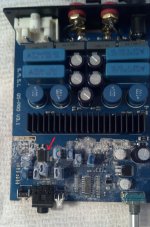
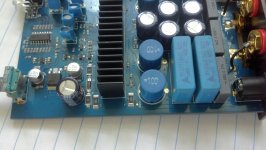
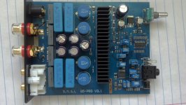
I have a SMSL SA60 mini amp. The problem is that the voltage regulator was shorted. While it still seems to be working it appears that other components were damaged. Before the short the voltage regulator had an input voltage of 18.37 and an output of 7.99 volts, now it has an input of 17 volts and the output is still the same; but nothing on the amp works anymore. The leds on the front don't light up, the volume doesn't work and there is no sound out of the speakers. Also since the short there is a chip on the board that gets excessively hot very quickly but I'm not sure what this chip is or what it does (It will have a red arrow pointing to it in one of the pics). The only other component on the board that even gets warm is the voltage regulator itself but it could be within its temperature range still. Any help with fixing this amp would be greatly appreciated. My understanding of circuits is not that great but I know some of the basics and have replaced blown capacitors and such before. I don't know how to test all the components but I do have a multi-meter and I can solder/de-solder components as necessary. If you have any questions or need more detailed pictures please let me know.
Also the two wires on the bottom are simply patch wires from the front aux input to the rear RCA's to give me a low level output , If you look closely you can see where the tracks connecting the RCA's to everything else were severed. This was done prior to the problem and worked fine.
Attachments
-
 IMG_20150505_190423_904-1.jpg892.8 KB · Views: 164
 -
 IMG_20150505_132450.jpg211.1 KB · Views: 78
 -
 IMG_20150505_131900_020.jpg511.7 KB · Views: 70
 -
 IMG_20150505_132225.jpg161.9 KB · Views: 60
 -
 IMG_20150505_132545.jpg175.4 KB · Views: 56
 -
 IMG_20150505_132600.jpg128.1 KB · Views: 70
 -
 IMG_20150505_132527.jpg182.9 KB · Views: 129
 -
 IMG_20150505_131415_993.jpg443 KB · Views: 130
 -
 IMG_20150505_132501.jpg179.7 KB · Views: 141
 -
 IMG_20150508_133412_259-1.jpg203.4 KB · Views: 144
Well if any voltage is dipping and the power supply is certain to be working then I would cut the power because something is shorted. Good thing the hot stuff has been identified.
What do you mean by "the voltage regulator was shorted. While it still seems to be working" - did a piece of wire go between the input and output? Did the original regulator die shorted and got replaced?
That picture does not look promising - it looks like at least one 47uF capacitor has spilled its guts everywhere, and likely most of the parts on board too. Likely beyond economical repair.
Okay since you don't have a response yet, I'll give it a go with my limited knowledge. The chip that gets hot is your pre-amplifier. The amp chip on the board under the sink is a fixed volume amp, so it has to have a pre-amp built in to change the volume. The chip in the middle is your logic board which mutes/unmutes the inputs to the amp under the sink. The sink is pretty superfluous anyway - these chips are extremely cool running because of their efficiency.
Bottom line, the board is dead unless you can confirm empirically that all the components are still okay except your chips and then replace those - but those are BIG "if"s.
The chip with the arrow to it is your signal pre-amp. It is getting hot because it probably can only handle 5-7 volts (I can't see the identifying numbers or I would know for sure.
It's hot because when you shorted the voltage regulator you overloaded it and effectively melted the traces inside it making it a very pretty looking resistor. That is all it is good for now.
Your amp chip is probably ine, it can handle up to 32 volts as long as you didn't short a pin on it.
Your logic IC if not running hot *may* be okay, but you said the LED's don't light up so I can only assume it is dead as well. It also has to be programmed so you have to assume that you won't be able to program that another dead end.
Also, it helps to know how the VR got shorted - so if you made a mistake or know how it got shorted, important to share it/own up to a mistake - we all make them. Just don't burn the building down with the hobby and I think you won't get much judging here")
Chalk this one up to an oops moment - you will waste hours trying to figure this one out... but in the meantime, find an acceptable replacement and get that running before you start tearing this one apart in an effort to learn how to diagnose.
I bought a nice little amp board recently that I like very much and has similar power. You can still get a nice STA508 with a TC2000 ADC front end with 80WPC for $15us shipped through overseas suppliers. Not the same efficiency but I really like the STA508 architecture along with the Tripath front-end. For me, having an isolated ADC from the power stage makes sense in concept and I think it translates to the result.
I'll post a picture of it. This will likely run just fine on the power supply you have for the amp that broke.
Sorry to bear bad news.
Bottom line, the board is dead unless you can confirm empirically that all the components are still okay except your chips and then replace those - but those are BIG "if"s.
The chip with the arrow to it is your signal pre-amp. It is getting hot because it probably can only handle 5-7 volts (I can't see the identifying numbers or I would know for sure.
It's hot because when you shorted the voltage regulator you overloaded it and effectively melted the traces inside it making it a very pretty looking resistor. That is all it is good for now.
Your amp chip is probably ine, it can handle up to 32 volts as long as you didn't short a pin on it.
Your logic IC if not running hot *may* be okay, but you said the LED's don't light up so I can only assume it is dead as well. It also has to be programmed so you have to assume that you won't be able to program that another dead end.
Also, it helps to know how the VR got shorted - so if you made a mistake or know how it got shorted, important to share it/own up to a mistake - we all make them. Just don't burn the building down with the hobby and I think you won't get much judging here
Chalk this one up to an oops moment - you will waste hours trying to figure this one out... but in the meantime, find an acceptable replacement and get that running before you start tearing this one apart in an effort to learn how to diagnose.
I bought a nice little amp board recently that I like very much and has similar power. You can still get a nice STA508 with a TC2000 ADC front end with 80WPC for $15us shipped through overseas suppliers. Not the same efficiency but I really like the STA508 architecture along with the Tripath front-end. For me, having an isolated ADC from the power stage makes sense in concept and I think it translates to the result.
I'll post a picture of it. This will likely run just fine on the power supply you have for the amp that broke.
Sorry to bear bad news.
Attachments
Thanks for the reply. Yes a piece of wire did short the input and output together and its still the original regulator. Which capacitor are you referring to? If its the one closest to the voltage regulator that looks crooked, it seems to be fine. I thought it could have been blown too, but I took it off the board and apparently there was just a poor solder connection on one leg to the board so it got bent over a little. Oh and I forgot to mention that I just spayed compressed air (upside down) onto the board in the first picture so I could find the hot components.
And as far as economical repair goes. I don't necessarily need all the features and modes to work. I planned on using it in a sort of powered speaker, so the amp volume would be set to max and input volume from the aux input would be used to control the actual speaker volume. The cost of a new one is around $80 so is there any way to get this to work as a straight forward amp? I believe it is based off the Texas Instruments TPA3116 board. At least that's what the products web page says.
And as far as economical repair goes. I don't necessarily need all the features and modes to work. I planned on using it in a sort of powered speaker, so the amp volume would be set to max and input volume from the aux input would be used to control the actual speaker volume. The cost of a new one is around $80 so is there any way to get this to work as a straight forward amp? I believe it is based off the Texas Instruments TPA3116 board. At least that's what the products web page says.
That picture does not look promising - it looks like at least one 47uF capacitor has spilled its guts everywhere, and likely most of the parts on board too. Likely beyond economical repair.
It more looks like ice from a coolant spray.
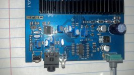
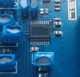
Thanks for the replies binely and doctormord. Sorry my posts are still delayed since I'm new and I didn't see your post binely until after I replied to wwenze. And yes the shorting was my doing, stupid mistake. But I show a close up of the signal pre amp in the second pic and it doesn't seem to have any ID marking on it at all, which I assume is unusual.
Also thanks for the info about the sta508. I would really like to fix this amp because its housing fits my project almost perfectly. But if it cant be fixed I will most likely go with the sta508.
Also thanks for the info about the sta508. I would really like to fix this amp because its housing fits my project almost perfectly. But if it cant be fixed I will most likely go with the sta508.
Last edited:
Well... hard to say then exactly how to do this. You'd need to remove the sink, find your signal input trace and then short the input trace to the input line though I suspect some of those components you can see are startup-mute circuitry so it would be fiddly with startup thumps and less protected from shorts. TI has the datasheet out there for the TPA3116d2 and I've played with these amps a bit (burned out two chips - yaay!) and one thing I've learned - be careful with SMD boards. A lot less tolerant of small mistakes than through hole projects.
Also, you'd do well to cut the traces to the inputs from any other sources so you don't get unintended feedback or oscillations.
Welcome to the world of modding. It means you will break a lot of stuff, and fix some of it. Sorry it had to be this board, but in the end you will know more for it. That is funny your pre amp chip has no markings. Def some sort of multi input op-amp design though, because the TPA has it's own ADC so any PWM would just be garbage to it unless there is some mode I don't know about that it enabled through a hardware pin setting somewhere on your board.
Cheers
I don't know if I would not use a regulator at all. That regulator at 18v is likely the feeder for the amp chip and the B+ will be pulling from those polycaps if not the electrolytic that I am willing to bet is fed from that regulator because they are smds and there aren't any underside traces for it.
I might replace it...
I might replace it...
Ok so I should remove the regulator so I can replace it? I can de-solder it no problem but then I tried finding a replacement I could not find one with the SF designation that mine has. Does anyone know what the significance of that marking is or where I could find a replacement?
Also this may be a stupid question but what exactly are you saying to do here?
I assume by "cut the traces" you want me to cut the tracks (same thing as traces?) on the board similar to the way I cut the tracks from the RCAs?
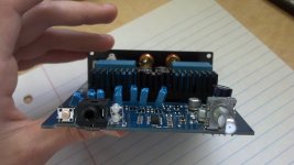
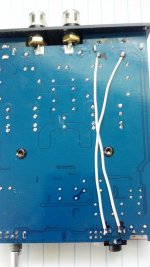
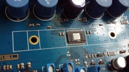
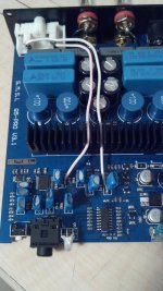
And I thought I would add this picture of what's under the heat sink since it might help.
Also this may be a stupid question but what exactly are you saying to do here?
Also, you'd do well to cut the traces to the inputs from any other sources so you don't get unintended feedback or oscillations.
I assume by "cut the traces" you want me to cut the tracks (same thing as traces?) on the board similar to the way I cut the tracks from the RCAs?
And I thought I would add this picture of what's under the heat sink since it might help.
Attachments
Sorry, I can get ahead of myself. Yes, you should replace the voltage regulator if it is putting out something else than what it did before. I don't know a ton about those but I do know that you need to need to find similar voltage and current capabilites. Most of the time letter codes are only specific to manufacturers so you can safely focus on the voltage/current aspect.
HOWEVER - I think you are missing the point. You need to know the other parts are okay. If you can't verify that first - then you are spinning your wheels and I can't help you with something even I have no idea what I'm talking about. There are lots of tutorials out there on youtube - prepare for a busy time learning it all.
HOWEVER - I think you are missing the point. You need to know the other parts are okay. If you can't verify that first - then you are spinning your wheels and I can't help you with something even I have no idea what I'm talking about. There are lots of tutorials out there on youtube - prepare for a busy time learning it all.
Ok I'll start checking other components and let you know what I find. But just to clarify, the regulator is still putting out the same voltage as it did before 7.99 volts. But its input changed from 18.36 to 17.0.
Thanks again for the help and if anyone else has any suggestions or questions about the board let me know and I'll try to answer the best I can.
Thanks again for the help and if anyone else has any suggestions or questions about the board let me know and I'll try to answer the best I can.
Typically in such a design, the amplifier chip is powered directly from the 12V or 18V or 24V or whatever voltage coming from the external power supply. However the control circuitry and other stuff need a lower voltage, which would be derived from a step-down regulator. The 78M08 in this case. (They come in 8V?)
Since you're going to bypass the entire lower-voltage part of the circuit and use the amp chip directly, (and the lower-voltage parts are presumably damaged) removing the regulator cuts off the supply to those parts and prevents further burning from any short.
I will remain wary of the input dropping from 18.37V from 17V in case there is another short that is lowering that voltage. Do check if the voltage goes back up after removing the regulator. What external power supply are you using? A 19V laptop power brick?
As for the new signal wires, for rach channel there would be a capacitor between the amp chip's "signal in" and the dead IC. Remove the capacitor and use the pad for soldering.
"78" is a type of fixed voltage regulator IC that is produced by many companies. Slight differences in naming, but all of them have a 78 followed by a 2 digit number stating the output voltage.
"78" is a type of fixed voltage regulator IC that is produced by many companies. Slight differences in naming, but all of them have a 78 followed by a 2 digit number stating the output voltage.
Last edited:
Thank you wwenze. I learned a lot from you in reading these. Agree about checking the voltage. I know I'm hijacking here a little - but if you are using a regulated supply, and it stays down like that, is it possible that the supply could be damaged, e.g. the optocoupler could have slightly damaged the led inside and that is why there it is derating the current? I have a similar situation in a regulated power supply that I'm troubleshooting.
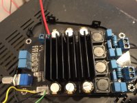
Alright I de-soldered the two legs of the regulator, is it necessary to remove the entire chip as long as the legs are disconnected? There is no voltage going through the regulator and the pre amp no longer gets hot. Also the voltage is back to where it was before the short. So that would mean the problem is fixed right?
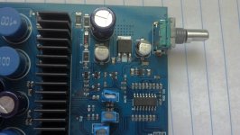
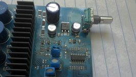
And just to be sure I understand before I go any further. basically I need to feed my input signal directly to the amplifier chip right? and to do that I need to solder a set of wires from the aux input to the bases where the left/right channel capacitors are. Correct?
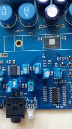
If so I think I've found the capacitors. But there seems to be two per channel, could that be right? They are located directly in between the pre amp and the main amplifier. I have accurately highlighted the tracks between the two in a picture below, the third picture is just the second picture unedited.
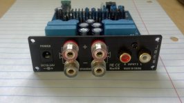
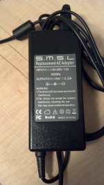
Also the power supply has a 19v 5.3A output and seems to be working fine. (Also pictured below)
And just to be sure I understand before I go any further. basically I need to feed my input signal directly to the amplifier chip right? and to do that I need to solder a set of wires from the aux input to the bases where the left/right channel capacitors are. Correct?
If so I think I've found the capacitors. But there seems to be two per channel, could that be right? They are located directly in between the pre amp and the main amplifier. I have accurately highlighted the tracks between the two in a picture below, the third picture is just the second picture unedited.
Also the power supply has a 19v 5.3A output and seems to be working fine. (Also pictured below)
Attachments
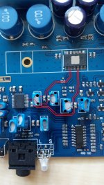
Yup - those traces match the in + and - (left and right respectively). However, the right speaker traces are on the left and the left speaker traces are on the right.
So, that's your connection points - but usually there are some input filters to be sure you aren't driving those pins to hard with audio signal. Check the datasheet - you may be able to use the chips on the board for that but I don't know what those values are for those filter elements and they could really sound terrible for your source. IF you were able to figure out what that chip is you might be able to replace it and avoid all that trouble.
However, before you bother with that, you should check that your other pins on the chip are showing the right voltages. This is pretty tricky because they are small and you will easily short them and break the chip too. But, as long as the amp chip is getting the right voltage and you can get some audio while it is powered up by testing the the audio in pins with some sort of signal, then it might work.
If it doesn't send audio out, then you have a problem with the mute control circuitry and that is out of my league.
The mute pin is the one to the right of the left speaker in pins. It has to be driven with the correct voltage to turn the audio on or off with the correct voltage. You'll have to read the datasheet to get that info.
I've done all I can. The rest is up to you.
Last edited:
Woohoo!! It works . I did what you said and read the spec sheet for the tpa3116 (yes the whole thing), checked all the voltages, ran two wires from the input to the legs of the capacitors shown previously that connect to the amp, and it works. Obviously I've lost all control of the front panel, but that doesn't matter for my intended use anyway. The only downside I have noticed is that sometimes if it is connected to a input source but the source is paused there will be a hum through the speaker, but as soon as you hit play it disappears completely. Not really a problem though just an observation. Both channels work correctly and I still have a pre-amp out through the rca's to go the subwoofer amp. Thank you all very much, you have saved me a lot of time and money and I greatly appreciate all the help.
(I just went from the RCA's to the capacitors since the RCA's are already directly connected to the auxiliary input and I thought it would look cleaner)
. I did what you said and read the spec sheet for the tpa3116 (yes the whole thing), checked all the voltages, ran two wires from the input to the legs of the capacitors shown previously that connect to the amp, and it works. Obviously I've lost all control of the front panel, but that doesn't matter for my intended use anyway. The only downside I have noticed is that sometimes if it is connected to a input source but the source is paused there will be a hum through the speaker, but as soon as you hit play it disappears completely. Not really a problem though just an observation. Both channels work correctly and I still have a pre-amp out through the rca's to go the subwoofer amp. Thank you all very much, you have saved me a lot of time and money and I greatly appreciate all the help.(I just went from the RCA's to the capacitors since the RCA's are already directly connected to the auxiliary input and I thought it would look cleaner)
Attachments
Congratulations!! Feels good doesn't it!
Yup, that's what I would have done. The hum is because you don't have a true vref signal going to the negative pins. If you want to take a risk, attach 2 wires to ground at the input and and run those to the other two caps. That will take away your hum for the most part.
When there isn't any signal coming through those wires right now, the amp thinks there is no signal and so you are getting hum from the feedback of the old traces that are mostly de-energized and providing a 0v gnd reference for the amp chip, when the signal in should also be providing the 0v ground reference with a complete return path. Right now that return path is pretty long.
But it works, it works! So if you are happy, then I am happy too!!
- Status
- This old topic is closed. If you want to reopen this topic, contact a moderator using the "Report Post" button.
- Home
- Amplifiers
- Class D
- Shorted voltage regulator on SMSL amp need help