I sensed the writing on the wall and used the Firefox Scrapbook plugin to grab a copy of much of the 41Hz website including some forums back in 2012.
Let me know what you are after exactly (I don't really have much on the AMP15-ps xp).
Do you have anything about amp2 and amp7?
Yes I have everything on AMP2 - I started building a bridged version of an AMP2.
I bought 2 boards, one for each channel. 1 board is partially completed.
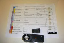
1st photo is the spreadsheet I made with parts placement & optimization calculator.
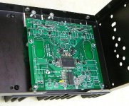
2nd photo is fitting of board in a Bryston 4B amp case.
The last photo is an AMP2 in a 1U case that V-bro made & sold.
For AMP7 I only have the design note.
I do have some TruePath dox which I believe is the predecessor to the Amp7. This includes some of Audiophools optimization notes.
I'm not sure how much I can post here without copyright infringement.
Some of the files were restricted to customers that actually purchased the kits.
It would be good to find out the status of 41Hz & if Jan has indeed shut down for good.
I bought 2 boards, one for each channel. 1 board is partially completed.
1st photo is the spreadsheet I made with parts placement & optimization calculator.
2nd photo is fitting of board in a Bryston 4B amp case.
The last photo is an AMP2 in a 1U case that V-bro made & sold.
For AMP7 I only have the design note.
I do have some TruePath dox which I believe is the predecessor to the Amp7. This includes some of Audiophools optimization notes.
I'm not sure how much I can post here without copyright infringement.
Some of the files were restricted to customers that actually purchased the kits.
It would be good to find out the status of 41Hz & if Jan has indeed shut down for good.
Attachments
Last edited:

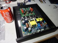
If you look closely in the 3rd pic above, you can see the jumper I added to bridge it (yellow insulated)
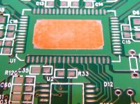
In photo 1 soldered a copper sheet under the chip.
In photo 2 you can see the heat sinks I bought to stick on the chip
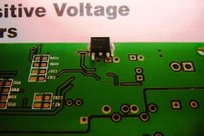
In photo 3 you can see the on-board MC7805 voltage regulator chip I added.
Sadly it has been sitting unfinished like this for the last 6 years.
Now that I am retired I plan on finishing these off as a winter project.
In photo 1 soldered a copper sheet under the chip.
In photo 2 you can see the heat sinks I bought to stick on the chip
In photo 3 you can see the on-board MC7805 voltage regulator chip I added.
Sadly it has been sitting unfinished like this for the last 6 years.
Now that I am retired I plan on finishing these off as a winter project.
Attachments

I see the jumper... to bad it is not jumper like with amp7, that could be call modding.. in any case, you can't do it very fast if you wanted to, but didn't ever look into it, what would it take.
I don't know why do you need CU sheet under the chip, it will raise the chip and make soldering harder, I wouldn't use it (I can see it is very slim)
First time I soldered it, it was the best, 2nd time I used thermal past, not as good, but still good enough. For top heatsink I use U shaped Al profile, nothing special.
If you will need any help or advice, come and find me!
Thanks Luka,
I did consider leading the jumper out to an external switch, but this can subject the input to extraneous noise. In any case, the amp is designed to as 2 bridged mono amps and will not be switched back to 2 channels each.
I see you have some info on your Amp2 build on your web site.
I'll let you know how the build goes when I get back into it this autumn during the long cold winter evenings.
There are no trimpots on the 41Hz AMP1.
I only see them in the reference design spec data sheet, which labels them as:
OUTPUT OFFSET NULL
There are two potentiometers, R54 and R55 that are used to manually trim the output offset to 0V.
41Hz AMP1 uses the Ver. 4.0 design which has auto offset nulling:
OUTPUT OFFSET NULL AND RELAY
There is an automatic offset trim circuit for each channel using an LM358 op-amp. Once the LM358
trims any DC to 0Vdc a comparator allows a relay to close.
Attachments
Last edited:
Hi Ryssen,
Based on your question, it appears you are building the early reference design amp and not the 41Hz Amp1?
Grounding is very important with these amps, especially the 5V supply.
On mine I used separate windings on the PS toroid to isolate the +5V supply ground from the +/- 30V PS ground.
Here is some detail around this from the 41Hz assembly instructions:
More details on grounding can be found in the attached Ver4.0 reference design doc.
Based on your question, it appears you are building the early reference design amp and not the 41Hz Amp1?
Grounding is very important with these amps, especially the 5V supply.
On mine I used separate windings on the PS toroid to isolate the +5V supply ground from the +/- 30V PS ground.
Here is some detail around this from the 41Hz assembly instructions:
The +5V is used for the analogue input amplifier and the in-chip digital parts of the TA2022. It needs to be well stabilized and well bypassed.
You can use a 7805 voltage regulator or similar by tapping current from the positive main supply. You can use a separate transformer supply to feed the 7805.
The +5V should be connected using shielded cable, to prevent it from picking up noise. The +5V will not draw more than about 60 mA.
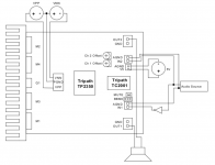
Hookup and shielding.
Switched mode amplifiers are a bit noisy by nature, in the sense that they emit EMI that is generated by the high power, high frequency output transistors.
This can be transmitted via cabling or as radiated in the atmosphere and picked up by other equipment like radios, preamplifiers etc or by the amplifier inputs.
It is therefore recommended that some precausions are taken. The most important is that the amp is housed in a metal/shielded casing.
Proper grounding is also important. Note that input ground should be taken to the board J2 connector ground, not to the housing or power supply ground.
The speaker returns should lead to J3 ground, not to the casing or power supply ground.
It is recommended that hookup cable for the signal input and +5V is shielded and as short as possible so that it does not pick up noise from the outputs.
Input cables and +5V cables should lead away from the outputs as far as possible.
Speaker cable and power cables can be twisted. All cables should lead the shortest way out of the casing.
More details on grounding can be found in the attached Ver4.0 reference design doc.
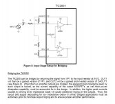
Three external power supplies are required to operate the EB-TA2022: VPP, VNN (referenced to
Pgnd), and 5V (referenced to Agnd). The VPP and VNN form a split rail supply referenced to Pgnd.
The 5V ground (Agnd) must be kept separate from the VPP and VNN ground (Pgnd). Agnd and Pgnd
are joined at a common point on the EB-TA2022 near headers J2 and J3.
Attachments
Last edited:
I've added 2 spreadsheets showing the 41Hz Amp collection as well as a folder with all the Tri-Path Application Notes on my Google drive here:
https://drive.google.com/folderview?id=0BxUZKhzrYS3iSUFqSlhWeG9faGs&usp=sharing
-=Cheers=-
https://drive.google.com/folderview?id=0BxUZKhzrYS3iSUFqSlhWeG9faGs&usp=sharing
-=Cheers=-
Very unlikely, even if he could get himself together, the industry has bounded well ahead of him, the sheer number of manufacturers of very decent amps, fully assembled for less money is mindboggling, you could argue that his amps are still better than what is out there now, but the difference would be small.
I've added 2 spreadsheets showing the 41Hz Amp collection as well as a folder with all the Tri-Path Application Notes on my Google drive here:
https://drive.google.com/folderview?id=0BxUZKhzrYS3iSUFqSlhWeG9faGs&usp=sharing
-=Cheers=-
I've added an AMP15 folder to the Google drive link above.
Download all files and folders to folder called AMP15 on your local PC.
You should then be able to open all .htm files in the AMP15 folder with the content in each associated folder.
- Home
- Amplifiers
- Class D
- 41Hz forum dump