Hi all-
I bought this item from ebay to convert an old 8" passive sub to active and use the LFE output on the surround processor as the active XO. I have several transformers laying around so I figured all I needed was the actual amp board.
The amp actually looks nice for the money but it came with zero documentation.
Has anyone used or know anything about the amp? Most pertinent question is the input connector and wiring. Where can I get a female connector for the amp since they didn't supply one, and since it is a mono amp, is it a balanced input, does it sum the left and right channels or do I need to sum them and feed dual mono to the amp?
Any information is appreciated.
Yes I wrote the seller.. No English, terrible responses and as he had hoped after a week of trying I gave up.. I have the emails if anyone would like to see the conversations...
IRS2092 Class D Mono Amplifier Amp Board 200W IRFI4019 | eBay
Hi!
I guess it's 1/2 of an IRAUDAMP7s. You can find info at IR:
http://www.irf.com/technical-info/refdesigns/iraudamp7s.pdf
Audio-in cable you can buy from Yan-Jing, with or without RCA connectors
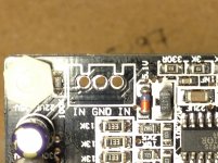
Or solder it directly. Pins should be: Left - Ground - Right
Yuan Jing Audio - Cables
I think it's their amp you bought:
Yuan Jing Audio - IRS2092 Class-D Mono Amplifier Board [200W] - $29.80 - Class-D & T
Cheers
Sten
I guess it's 1/2 of an IRAUDAMP7s. You can find info at IR:
http://www.irf.com/technical-info/refdesigns/iraudamp7s.pdf
Audio-in cable you can buy from Yan-Jing, with or without RCA connectors
Or solder it directly. Pins should be: Left - Ground - Right
Yuan Jing Audio - Cables
I think it's their amp you bought:
Yuan Jing Audio - IRS2092 Class-D Mono Amplifier Board [200W] - $29.80 - Class-D & T
Cheers
Sten
Troystg: did you ever get this amp up and running?
I'm interested in trying out one of these modules. I happen to have some power supplies that would be perfect for them.
The lack of specs like distortion performance, etc. has me a bit concerned, but for $20 as long as I know that I can get it up and running I might get one or two and test them.
I'm interested in trying out one of these modules. I happen to have some power supplies that would be perfect for them.
The lack of specs like distortion performance, etc. has me a bit concerned, but for $20 as long as I know that I can get it up and running I might get one or two and test them.
Negative.. Once I couldn't get any specs for it I put it aside...
I saw where I could get the input cable but since it is a stereo cable and this is a mono amp I didn't know if I needed to build a summing network or if one is on board..
Not a project I wanted to pursue at this time since the documentation is incomplete..
Sorry.
I saw where I could get the input cable but since it is a stereo cable and this is a mono amp I didn't know if I needed to build a summing network or if one is on board..
Not a project I wanted to pursue at this time since the documentation is incomplete..
Sorry.
I started a thread here concerning this amp.
The power supply has to be symmetrical. I used one from hifimedy (it is in fact one from connecelectronics.com) SMPS300RE +-45V (DUAL VOLTAGE) 230V POWER SUPPLY with success.
The input is not left - GRD - right but left/right GRD left/right. Being mono amps each has one input only. Both terminals on either side of the GRD are the same as far as I can tell.
I destroyed one of my amps trailing different power supplies. Only use a symmetrical dual voltage PS.
Hope this helps.
PS you can get them cheaper from aliexpress.com ;-) I got my first ones for 13$, they are now around 15$
...The input is not left - GRD - right but left/right GRD left/right. Being mono amps each has one input only. Both terminals on either side of the GRD are the same as far as I can tell....
Thank you for commenting but...
Is this documented some where or are you guessing?
Most of my electronics and speakers cost more than this unit. It is not worth damaging a driver on guesses.
Thanks anyway but I'll leave it in a drawer until I have the actual documentation.
Which is a shame because it looks like a neat little unit.
No, I have a pair of old speakers I test my newly built / assembled amps on. So no worries even if I fry them.
Concerning the inputs, I tested them. Someone suggested they where balanced and to short one of the two inputs to GRD but that didn't work. I don't know why the designer of this amp decided to have two identical connection points ??
When you get the documentation, please post it here. I have asked YF but haven't had any luck so far. So I juste tested the board "in situ". Considering the price the complete amp is it wasn't too much of a risk.. but yes, I did fry one of the two I had bought for 13$/piece
No, I have a pair of old speakers I test my newly built / assembled amps on. So no worries even if I fry them.
Concerning the inputs, I tested them. Someone suggested they where balanced and to short one of the two inputs to GRD but that didn't work. I don't know why the designer of this amp decided to have two identical connection points ??
When you get the documentation, please post it here. I have asked YF but haven't had any luck so far. So I juste tested the board "in situ". Considering the price the complete amp is it wasn't too much of a risk.. but yes, I did fry one of the two I had bought for 13$/piece
Thanks for your posts in this thread and link to the other. I purchased a pair of these and they should arrive in about three weeks or so. For me the question was only about the 3-pin input connector, so again thanks for the info on that. The PS connection and SPKR connection is pretty clearly marked.
@Troystg: you are never going to get "specs" or "documentation" for this amp board. This is the nature of the beast with many of the Chinese products on Ebay. You need to know something about them in advance, and what you can discern from the pics, and then take a leap of faith. Once you get the item, never just put it in the signal chain connected to any real Hi-fi equipment. I will initially connect this to an old woofer for testing, and then work my way up to a real speaker and then eventually my test equipment. Don't put the expectations too high - I have junked some Ebay stuff right away, but I have also managed to find a few diamonds along the way.
Once I couldn't get any specs for it I put it aside...
I found a very similar looking amp on Ebay. Looking at the different pics of different angles seems to indicate that they are the same layout, etc. so likely the same design (lots of copying going on in China):
IRS2092S 250W Class D HiFi Digital Power Amplifier Board LM3886 | eBay
Here are the specs listed:
Specification :
Supply voltage : Dual DC power ± 42 --- ± 58V
Rated output power : 250W (± 50V supply 4 ohm speakers, Distortion < = 0.05% )
Maximum output power : 300W (± 50V supply 4 ohm speakers, Distortion < = 2% ) , for work at the maximum power Please enhance heat dissipation , the board is rated at 250W)
Efficiency: > = 90%
SNR : 90dB
Total harmonic distortion : 250W (± 50 Power 4 ohm speakers, Distortion < = 0.05% )
250W (± 50 power 8 ohm speakers, Distortion < = 0.01% )
Frequency range : 20Hz-20KHz
Speaker :4-8Ω
Voltage gain : 36 times
Output short circuit protection : Yes
That speaker output DC bias protection protection:
Undervoltage protection: , 39V, 39V power amplifier supply voltage is lower than would be protected off the output !
Overvoltage protection: There , 68V, 68V power amplifier will be higher than the supply voltage protection , turn off the output !
Over Temperature Protection: Yes, radiator FET temperatures above 100 ° C, close the output !
Amplifier board size: LxWxH = 86mm * 56mm * 29mm
Weight: 100 grams
Note:
1, rated as dual power supply voltage ± 50V, the voltage at ± 42 --- ± 58V can work properly , because this amp has undervoltage and overvoltage protection , it is recommended not to lead nearly voltage supply voltage protection point , because if the power when power voltage fluctuations, if the voltage is below or above the range of instantaneous protection , the protection and shut down the amplifier output, and staccato , not to reverse the positive and negative power supply
2 power supply recommended ± 50V DC dual power supply filtering better
3 recommended 6-10 inch speaker 4 ohm or 8 ohm speakers
4 Although the audio output short circuit protection , but try not to short-circuit
5 Please check carefully before electricity , ensure the wiring is correct before pass .
6 . Circuit wiring diagram above icon note .
7 This plate voltage is fixed at 36 times magnification , if the output power is not enough, as the case may add their own preamp
Thanks for your posts in this thread and link to the other. I purchased a pair of these and they should arrive in about three weeks or so. For me the question was only about the 3-pin input connector, so again thanks for the info on that. The PS connection and SPKR connection is pretty clearly marked.
yeap, the other connections are quite clearly marked. These amp boards are a bit of a mystery to me but I think they could hold some potential for a good sounding amp at a very low price.
I found a very similar looking amp on Ebay. Looking at the different pics of different angles seems to indicate that they are the same layout, etc. so likely the same design (lots of copying going on in China):
IRS2092S 250W Class D HiFi Digital Power Amplifier Board LM3886 | eBay
...
yes, indeed the layout looks quite similar. They say something about the LM3886 ?
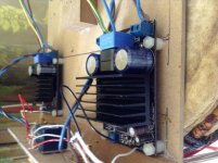
i just got the new amp from China to replace the one with the hot inductor. It is from the same supplier but has different caps mounted on it. The first two amps had black Nichion caps. this one has blue no-name caps.
I will keep it running for a couple of days and see how it works out
Greets
I will keep it running for a couple of days and see how it works out
Greets
Attachments
I have bought some similar looking amps but with NXP8950th IC. They also came with no documentation at all, and seller can't answer even simple questions like how the BTL configuration works. I know this chip very well, but without schematics it's only trial and error. Personally I have dumped these very very cheap modules for now.
When you have to calculate som losses on bad modules, and you need a good PSU and cabinet it all adds up, and get very close to cheap PA class D amps (completely finished).
When you have to calculate som losses on bad modules, and you need a good PSU and cabinet it all adds up, and get very close to cheap PA class D amps (completely finished).
i just got the new amp from China to replace the one with the hot inductor. It is from the same supplier but has different caps mounted on it. The first two amps had black Nichion caps. this one has blue no-name caps.
I will keep it running for a couple of days and see how it works out
Greets
How's it going so far?
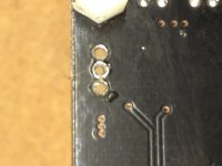
From the pic you posted it seems you unsoldered the 3-pin input connector and soldered the input signal wires in place. Is that correct?
Can you confirm that you found that both of the "in" pins connect together? Did you test that? If you have removed the input signal connector housing, can you see a trace connecting the two outer pins?
I just received my boards today and I am getting ready to test them out. I haven't decided what to do with the input connector and since the seller didn't provide a mating cable assembly I can use it without modification.
Last edited:
How's it going so far?
From the pic you posted it seems you unsoldered the 3-pin input connector and soldered the input signal wires in place. Is that correct?
Can you confirm that you found that both of the "in" pins connect together? Did you test that? If you have removed the input signal connector housing, can you see a trace connecting the two outer pins?
I just received my boards today and I am getting ready to test them out. I haven't decided what to do with the input connector and since the seller didn't provide a mating cable assembly I can use it without modification.
Yes, I desoldered the 3-pin connector and I think I can make out a trace between the two "IN" pins on the top of the board.
Attachments
I use this connector for my boards with similar input
50 pcs 3 Pin/way 2.54mm Connector XH 3P plug with 10cm cable for Electronic model / Automobile/PCB ect.Free Shipping-in Connectors from Electrical Equipment & Supplies on Aliexpress.com | Alibaba Group
50 pcs 3 Pin/way 2.54mm Connector XH 3P plug with 10cm cable for Electronic model / Automobile/PCB ect.Free Shipping-in Connectors from Electrical Equipment & Supplies on Aliexpress.com | Alibaba Group
I use this connector for my boards with similar input
50 pcs 3 Pin/way 2.54mm Connector XH 3P plug with 10cm cable for Electronic model / Automobile/PCB ect.Free Shipping-in Connectors from Electrical Equipment & Supplies on Aliexpress.com | Alibaba Group
Thanks for the link! I might get some - it seems this is bog standard for stuff coming out of China...
I have tons of screw terminal blocks with 0.1" spacing, so I will just install a 2-pole version to connect signal GND and IN.
- Status
- This old topic is closed. If you want to reopen this topic, contact a moderator using the "Report Post" button.
- Home
- Amplifiers
- Class D
- ebay IRS2092-Class-D-mono-amplifier help