thanks for clarifying, one friend bought a supposedly TDA7498E board like this in your link but together with an aluminium enclosure; the chip fried after some experiments and after taking out the heatsink he found out that the chinese supplier sold him a plain TDA7498 without "E"; after this he ordered a genuine "e" chip from mouser and now he is happy with it; did you had the curiosity to look under that heat sink?
also, do you happen to know what value are those chokes on the output? are they in the 10-15 uH range to be suitable for 4 ohm loads or would I have to buy other ones?
I found these 2 options on ebay, maybe you can take a look
Coilcraft DO5010H-123ML 12uH inductor Irms=5.2A, Isat=8.5A, 28milliohms | eBay
5pcs 10uH 7.5A Small Toroidal Inductor Magnet inductance Coil Anti-Interference | eBay
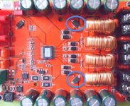
To cheat and mount a TDA7498 instead of a TDA7498E is a lousy thing to do if it was sold as a TDA7498E. Replacement requires a steady hand. I had the curiosity when I shorted the polarity protection diodes and mine is a real TDA7498E.
The chokes on Chinese boards are often a guess. The chokes on this red board use red cores which is the better. Exact value?
NXP (formerly Philips) suggests 10uH/1.5uF for 4 Ohm loads, 15uH/1uF for 6 Ohm loads and 22uH/680nF for 8 Ohm loads. NXP is generally a very competent company. But, the values need not be exact and 15uH/1uF can be used in case of doubt for 4-8 Ohm. I would try the initial ones for a start without replacement.
Chinese chokes: I know three types - red core (the better with lower permeability but higher current before saturation and probably less abrupt saturation), black core
5pcs/KS065060 17MM Iron silicon aluminum 15UH 1.2 Line 10A Magnetic ring inductors Annular inductance-in Inductors from Home Improvement on Aliexpress.com | Alibaba Group
3pcs/23MM 22UH 1.3 Line Iron silicon aluminum Magnetic ring inductors Annular inductance 90 125A 15A-in Inductors from Home Improvement on Aliexpress.com | Alibaba Group
(which I have used with success) and blue/green/yellow-ish (which I cannot recommend as they seem to have very high core losses - I have tried them).
Toroidal cores are color coded according to characteristics but unfortunately every manufacturer uses his own codes and we do not know the manufacturer:-((
The first ("Coilcraft") choke you suggest is a semi open SMD type. The semi open may leave quite some stray-fields (noise) and I have only seen such used for low power amplifiers. I have no experience myself.
The second type you suggest is a toroidal choke on a blue/green/yellow-ish core, hence, with important core losses according to my experience.
I have tried the two black-core types shown above with good results.
I connected the capacitor without shorting the polarity diode. Why do I need to short this?
You "need" not do it but I did it. The reason is that if I want my external decoupling capacitors to assist the onboard capacitors the best, I do not want a voltage drop from the diodes in-between. I want the supply voltage charge to be available with as little impedance as possible.
I agree with your observations of the balance between expensive speakers and cheap amplifier. At the other hand I think most of these amplifiers are not balanced as well as the quality of the chip in many cases is better than the rest of the board.
Buying these cheap boards is somehow addictive the more I know of it, although I have some failing ones you are aware of.
The amplifier chip sets the limits of the complete amplifier and the external components should be selected to match the chip quality. But, class D chips are often very cheap and many buy because they see "TDA7498" at an attractive price without considering if the amplifier implementation is well made.
I bought a Bluetooth+TPA3110 board (it worked) but realized that the quality of the TPA3110 is above that of the Bluetooth chip. It is one board so I cannot change that implementation. Next time I bought an external
HIFI Class Bluetooth 4.2 Audio Receiver Amplifier Car Stereo Modify Support APTX Low Delay-in Wireless Adapter from Consumer Electronics on Aliexpress.com | Alibaba Group
to use with a separate amplifier and the combined result was much better. Should the amplifier fail, I still have the Bluetooth receiver.
The 7498E board with fan you discussed in your former post has good chokes, but the capacitors to me seem very small. Are these folie capacitors? The pp capacitors I use for crossover filters are larger.
These are polypropylene foil capacitors if I am not mistaken. Standard quality but OK. Can be found even better (lower ESR) but is it worth spending perhaps another 6 EUR on a 16 EUR amplifier for a more marginal improvement?
Why are cross-over capacitors larger? (oh, it is decades ago I build my own speakers). I looked at various cross-over filters for loudspeakers and found that they typically use 5uF-50uF bipolar capacitors. Thus, a first reason is the difference in value. Next, the class D output filter capacitors do not carry the current in the speaker units (many of the cross-over capacitors do) as they only carry the ripple current from the PWM modulated signal (300KHz-400KHz). The cross-over capacitors carry a much higher ripple current and accordingly need lower ESR. A second reason for the difference in physical size.
Last edited:
Ok, I understand but why not connecting the additional capacitor to the capacitors on the board? Then its not needed to short the protection.You "need" not do it but I did it. The reason is that if I want my external decoupling capacitors to assist the onboard capacitors the best, I do not want a voltage drop from the diodes in-between. I want the supply voltage charge to be available with as little impedance as possible.
Another question: I am thinking of combining different amplifiers for active loudspeakers for instance 7598E for woofer and 7498 for tweeter. Does this give any complications?
Could you please advise me which TDA7498 board i should buy ?
8 Ohm speakers
I can vouch for my sanwu blue board for 8 ohm. You don't have to modify anything at all. In my opinion the board has better build and better components. Price difference isn't that big also. For cheap SMPS use a capacitor at power input as FauxFrench suggested or can build a capacitance multiplier as I have done. Totally worth it.
Aiyima TDA7498 Amplifiers Digital Stereo Power Audio Amplifier Board 2X100W Amplificador Dual Channel Speaker Impedance 8 ohms-in Amplifier from Consumer Electronics on Aliexpress.com | Alibaba Group
Price has gone up since I have bought it.
Are these two diodes you're talking about?You "need" not do it but I did it. The reason is that if I want my external decoupling capacitors to assist the onboard capacitors the best, I do not want a voltage drop from the diodes in-between. I want the supply voltage charge to be available with as little impedance as possible.
.
Attachments
@ zek
yes...these are the diodes
go back to
Ebay cheap TDA7498 boards
go back to page 44 i did some measuremnts and Fauxfrench help...as usal
the fan is starting about 41 °C and blowing quite silent to the point i measure 37 °C and then it stops.
chris
yes...these are the diodes
go back to
Ebay cheap TDA7498 boards
go back to page 44 i did some measuremnts and Fauxfrench help...as usal
the fan is starting about 41 °C and blowing quite silent to the point i measure 37 °C and then it stops.
chris
Thank you for reminding me, I'm a little older, so I forgot.

Ok, I understand but why not connecting the additional capacitor to the capacitors on the board? Then its not needed to short the protection.
Another question: I am thinking of combining different amplifiers for active loudspeakers for instance 7598E for woofer and 7498 for tweeter. Does this give any complications?
You are right, if you can put the additional capacitors on the board itself, you need not short the diodes. Perhaps you can arrange them on the rear side.
You probably mean (TDA)7498E and, with an electronic cross-over, you can combine the 7498E with a 7498. You can even use a class AB amplifier for mid-range and treble, if you like. The bass demands the most power.
I see that you took off the aluminium radiator, is your chip variant also with "E"? is that fan on top always blowing air for cooling or it kicks in just on high power demand? I might buy one of these boards
Mine is a real TDA7498E, bought for 13,12 EUR at a lucky moment.
Im planing to build a 2.1 boombox with detachable speakers and amp module.
The speakers I have are these ones:
2 Klipsch Quintet II satellites 8ohms rated 50W RMS, 90db/1w sensitivity.
1 Dayton DCS165-4 subwoofer 4ohms rated 100W RMS
I will be using 2 of these TDA7498E boards TDA7498E 2X160W Dual Channel Audio Amplifier Board, Support BTL Mode 1X220W Single Channel, for Car Vehicle Computer-in Amplifier from Consumer Electronics on Aliexpress.com | Alibaba Group along with this 2.1 preamp Free shipping NE5532 2.1 channel subwoofer preamp amplifier board Low Pass Filter Board-in Amplifier from Consumer Electronics on Aliexpress.com | Alibaba Group
One will be used in normal mode for the satellites and the other one in PBTL mono mode for the subwoofer.
What power supply voltage and amperage would you recomend me to get the most output power to these speakers.
Also I have a Dewalt 20V 4AH battery to use as a portable system. With this battery, what would be the max output power of each board to the speakers?
Last edited:
I have experience with these two power supplies:
AC DC Inverter Module 110V 220V 100 265V to 36V 5A Adapter Switching Power Supply-in Switching Power Supply from Home Improvement on Aliexpress.com | Alibaba Group
30v 5a switching power supply ac dc adapter 30v5a 30v dc voltage regulator 150w power supply-in AC/DC Adapters from Home Improvement on Aliexpress.com | Alibaba Group
Both worked with my TDA7498E board.
Another power supply of interest:
Aliexpress.com : Buy 36V 9.5A 350W Switching power supply special for digital power amplifier from Reliable switch power suppliers on Maria's shop
You write:...to get the most output power to these speakers.". The maximum supply voltage allowed is 39V. 36V is standard and leaves a small margin.
36V allows for 72 watt in 8 Ohm and 144 Watt in 4 Ohm. 72+72+144=288 Watt in total.
It has for long been debated if it is better that the amplifier power matches the speaker power, the amplifier power exceeds the speaker power or the amplifier power does not reach the speaker power. In all cases your speakers are not safe:
If the amplifier starts distorting heavily it looses control with the movement of the speaker coil and cone and the speaker may be damaged. If the amplifier supplies too much power to the speaker it may overload the speaker and the speaker is damaged. With the amplifier power matching the speaker power the amplifier will start distorting at a point where the speaker is already stressed to a maximum and the speaker may be damaged.
Personally I prefer a more powerful amplifier but I NEVER APPROACH THE MAXIMUM POWER OF THE SPEAKER.
I am not at all a speaker specialist. You can ask the speaker specialist on this forum for advice.
In your case a supply voltage of some 30V will leave the amplifier power to match the speaker power.
If you go for maximum amplifier power, 2 of the 180W types supplies (one for each amplifier board) or one 350W board for both boards should do.
I do not know the 350W supply but it seems to be designed with digital amplifiers in mind (an advantage as the regulation loop speed may be adapted).
You will convert one board into PBTL mono mode yourself?
The Dewalt battery will allow around 20 Watt in 8 Ohm. You have 2 channels so 40 Watt for the satellite speakers. In 4 Ohm you will get a maximum of 40 Watt for the subwoofer. In total 80 Watt.
Therefore, at full power with this battery you have a maximum operation time of 1 hour.
In reality (with music) the battery may do for around 4 hours but it is not going to be a long party.
Last edited:
I have experience with these two power supplies:
AC DC Inverter Module 110V 220V 100 265V to 36V 5A Adapter Switching Power Supply-in Switching Power Supply from Home Improvement on Aliexpress.com | Alibaba Group
30v 5a switching power supply ac dc adapter 30v5a 30v dc voltage regulator 150w power supply-in AC/DC Adapters from Home Improvement on Aliexpress.com | Alibaba Group
Both worked with my TDA7498E board.
Another power supply of interest:
Aliexpress.com : Buy 36V 9.5A 350W Switching power supply special for digital power amplifier from Reliable switch power suppliers on Maria's shop
You write:...to get the most output power to these speakers.". The maximum supply voltage allowed is 39V. 36V is standard and leaves a small margin.
36V allows for 72 watt in 8 Ohm and 144 Watt in 4 Ohm. 72+72+144=288 Watt in total.
It has for long been debated if it is better that the amplifier power matches the speaker power, the amplifier power exceeds the speaker power or the amplifier power does not reach the speaker power. In all cases your speakers are not safe:
If the amplifier starts distorting heavily it looses control with the movement of the speaker coil and cone and the speaker may be damaged. If the amplifier supplies too much power to the speaker it may overload the speaker and the speaker is damaged. With the amplifier power matching the speaker power the amplifier will start distorting at a point where the speaker is already stressed to a maximum and the speaker may be damaged.
Personally I prefer a more powerful amplifier but I NEVER APPROACH THE MAXIMUM POWER OF THE SPEAKER.
I am not at all a speaker specialist. You can ask the speaker specialist on this forum for advice.
In your case a supply voltage of some 30V will leave the amplifier power to match the speaker power.
If you go for maximum amplifier power, 2 of the 180W types supplies (one for each amplifier board) or one 350W board for both boards should do.
I do not know the 350W supply but it seems to be designed with digital amplifiers in mind (an advantage as the regulation loop speed may be adapted).
You will convert one board into PBTL mono mode yourself?
The Dewalt battery will allow around 20 Watt in 8 Ohm. You have 2 channels so 40 Watt for the satellite speakers. In 4 Ohm you will get a maximum of 40 Watt for the subwoofer. In total 80 Watt.
Therefore, at full power with this battery you have a maximum operation time of 1 hour.
In reality (with music) the battery may do for around 4 hours but it is not going to be a long party.
Wow, you helped me a lot.
Those power ratings are RMS or peak? For example those 20W per channel to the Klipsch satellites when using the battery.
If I use the battery and run the amp to a point where it outputs 16W to each klipsch speaker (90db sensitivity) the max SPL at 1m should be at 102db?
Last edited:
Those 20W are RMS (all power I mention is based on RMS voltages) provided that the battery can maintain a voltage of 20V with this (total) load current.
For the dbSPL, I had to consult the intelligent guys on the Internet. And, indeed, 16Watt will increase the sound pressure level with 12db compared to that at 1Watt.
For my own speakers it is more simple as there are only three sound levels: "too loud", "far too loud" and "TURN IT DOWN!". These levels are defined by my wife and more related to mood than to a particular SPL. At least I do not need to make any calculations in db.
Last edited:
Guys,
I burned the other board and bought the below one. I don't want to burn this board also. So need you help to build this one successfully.
I have attached picture of the transformer which gives 32v. I found that , the preferred voltage for this board is 24v with current more than 3amp. my question is below
1. How to step down 32v to 24v ? Any recommendation for regulators ?
2. I am not sure how much current the transformer produce like 3amp or 6amp ? Need a help to identify this.
3. My receiver has single mono input for the subwoofer. this board has left and right input. Is it ok to connect only left or right input line and use only one subwoofer ?
100W-100W-Amplifier-TDA7498-Class-D-Amp-Subwoofer :
2017 100W + 100W Amplifier TDA7498 Class D Amp Subwoofer Assembled Board Module | eBay
https://s17.postimg.org/eoklh0lan/20180218_010222.dng.jpg
Last edited:
Looks like you're going to burn something again.
First of all, the transformer can not be directly connected to the board, an PSU must be made at 24-32V DC.
How are you going to bring a subwoofer signal to the board?
First of all, the transformer can not be directly connected to the board, an PSU must be made at 24-32V DC.
How are you going to bring a subwoofer signal to the board?
Did you mean mono output for the subwoofer?My receiver has single mono input for the subwoofer.
Last edited:
Looks like you're going to burn something again.
First of all, the transformer can not be directly connected to the board, an PSU must be made at 24-32V DC.
How are you going to bring a subwoofer signal to the board?
Did you mean mono output for the subwoofer?
I am not going to directly use transformer output. The transformer is connected to the exiting CD player board which has rectifier circuit. I am taking the output from the rectifier circuit.
Look at the receiver subwoofer preout image .
https://cdn6.bigcommerce.com/s-8em24nxp/product_images/uploaded_images/rec-sub.jpg?t=1438710211
I am planning to use the audio cable like below image
https://pisces.bbystatic.com/image2...531/4531004_sa.jpg;maxHeight=640;maxWidth=550
For your TDA7498 amp you can use 24-32V DC.
If you didn't buy subwoofer yet, try to find some with two coils on it, and you can connect both outputs from the board. In this case you should connect two inputs together (L&R) and use that cable you post.
I already have this subwoofer . it's single voice coil woofer
https://www.bestbuy.com/site/boss-chaos-exxtreme-10-single-voice-coil-4-ohm-subwoofer-black/5909413.p?skuId=5909413
My question is, the subwoofer preout has single output but TDS7498 has both left and right input. Do i need to connect same input to bith L & R or just connecting L or R alone is enough ?
My question is, the subwoofer preout has single output but TDS7498 has both left and right input. Do i need to connect same input to bith L & R or just connecting L or R alone is enough ?
You could theoretically go from the sub out to both L + R input of the amp - but that does not help you at all since the TDA7498 is already a bridged IC amplifier. That means you can only use one channel output. Connecting both outputs parallel will destroy the amplifier (and would only give you more power at a lower impedance anyway).
About the power: Well, that's a 4 Ohm subwoofer. The TDA7498 isn't rated for 4 Ohm, it gets too hot, that exceeds the maximum current. You can still use it but you won't get the maximum power out of it (bit below 50W) and you should stay below 22V power supply. To get more power at 4 Ohm you could get a TPA3116 D2 mono amplifier board, these are actually rated for 4 Ohm.
- Status
- Not open for further replies.
- Home
- Amplifiers
- Class D
- Ebay cheap TDA7498 boards