ok Kalar, read thru it and a few pages after. Quite discouraging to hear my board is cheap junk! I hook it up with less than rec. power supply but thought it wasn't junk sounding? So I went into garage and hooked it back up, played jazz, latin, and jazz funk and it sounded ok but had a harsh treble sound like before. Bass was tight and present thru the 8"woofer in my Klipsch floor standers. I didn't have 1000uf cap but tries 220 and 2.2 parallel with the power input and no change. Then while handling amp I felt a fuzzy feeling touching heat sink. Unpluged it and removed the heatsink. After removing heatsink the harshness was gone! there is two plastic washers under heatsink where the mounting screws go. they are not as thick as the distance from board to top of chip where heatsink makes contact so when screws are tightened it pulls the pcb up in a curve. Must have been hitting one of the components under the heatsink causing short? so I will investigate further and measure aand apply standoff to properly clear the underneath components or use plastic from milk jug as shielding or something?
the board I have is not identical to post 67, 68 board. 1:it is blue not black 2:the pos speaker leads are both on the outside of the board. that is all I can distinguish at my knowledge level. I think it sounds pretty dam good for a junk board. I am not saying it is the end all but not junk. so I will get the 24v 6 amp brick nd try it? are those 330 inductors really that crappy? what does the 39k do exactly-its smd? what about the output stuff? especially the 5wat 2.2 ohm so exactly? the poster is far more knowledgable than I but I wonder if it was all because of the polarity issue? or will this amp with his mods sound that much better with them?
the board I have is not identical to post 67, 68 board. 1:it is blue not black 2:the pos speaker leads are both on the outside of the board. that is all I can distinguish at my knowledge level. I think it sounds pretty dam good for a junk board. I am not saying it is the end all but not junk. so I will get the 24v 6 amp brick nd try it? are those 330 inductors really that crappy? what does the 39k do exactly-its smd? what about the output stuff? especially the 5wat 2.2 ohm so exactly? the poster is far more knowledgable than I but I wonder if it was all because of the polarity issue? or will this amp with his mods sound that much better with them?
Poster was just frustrated with the board he had. Just replace those white resistor with wire. Sound quality will improve. Also make sure those inductors don't get too hot. You can also remove those yellow cap and replace with proper values as per data sheet for 8 ohm speakers. For 33uH 0.22uF or 22uH 0.47uF. After testing you can add a 1000uf >= 35v at the input of the power Jack.
the capacitors on my sanwu tda7498 board have swelled up and now I hear a lot of static thru the speakers. Any idea what might have caused this?
I've been running it off a 32v 625ma power brick from a printer, powering a pair of 8 ohm speakers rated at 100w each.
Got a new board on the way, would love to know how to avoid destroying the next one. Did I under-power it?
Pics of the damage: Imgur: The magic of the Internet
I've been running it off a 32v 625ma power brick from a printer, powering a pair of 8 ohm speakers rated at 100w each.
Got a new board on the way, would love to know how to avoid destroying the next one. Did I under-power it?
Pics of the damage: Imgur: The magic of the Internet
hi whiz, kalar uses 24V 6A on his. Chip is rated for up to 44V max, power cap is rated for 36V or 35? why wont 24V 6Amp brick be "way" too much? on 19V 3.7Amp brick chip don't even get more than slightly warm at moderate levels. WHy is it recommended to direct wire to board? is the barrel jack no good? why? been listening and the sound is damned good stock to my ears. smooth, dynamic, good bass amd vocals and treble. I could be very happy just the way it is but will give it more power for less sensitive speakers. If I read correctly on data sheet that they recommend output filters for this as are on my board but some different values? for 8 ohm load
the capacitors on my sanwu tda7498 board have swelled up and now I hear a lot of static thru the speakers. Any idea what might have caused this?
I've been running it off a 32v 625ma power brick from a printer, powering a pair of 8 ohm speakers rated at 100w each.
Got a new board on the way, would love to know how to avoid destroying the next one. Did I under-power it?
Pics of the damage: Imgur: The magic of the Internet
Those caps are rated for 35V, dangerously close to your PSU's Voltage. Replace those caps for higher voltages one.
Sailormanbgd, I haven't seen the question for the 39k resistor before? This resistor along with another one is controlling the gain. My board has onboard switch for gain settings. Your board doesn't have it. So if you want to change the gain (as this board has come with the highest gain probably) you can replace those resistor for lower gain as per data sheet. This will lower all kinds of noises. But I'll recommend first to do other easy mod and see what happens.
Sorry I have not noticed that SMD caps are available in the 10uF value.10uF/50V ceramic capacitors should be available at very reasonable prices. 10pF won't do much in this context.
the capacitors on my sanwu tda7498 board have swelled up and now I hear a lot of static thru the speakers. Any idea what might have caused this?
I've been running it off a 32v 625ma power brick from a printer, powering a pair of 8 ohm speakers rated at 100w each.
Got a new board on the way, would love to know how to avoid destroying the next one. Did I under-power it?
Pics of the damage: Imgur: The magic of the Internet
Better replace the fake Sanyo electrolytics on your new board too then.
can someone spec the best bang for buck caps to use on the 1 ower supply caps
2utput filter caps. I have no idea what brand, model works good for audio to replace these Chinese poor caps or fake whatever? I have 4 different boards-Bluetooth, 7498 with silver smd caps, and another with green EL-fake sanyo's? and one of the ME mono boards.
also, if someone knows what inductors to purchase to change out the 330 black box smd ones on the Bluetooth board would be appreciated too! the black ones get as warm as the chip with only 19V and have ordered 24V. thanks 8 ohm speakers
ower supply caps2
utput filter caps. I have no idea what brand, model works good for audio to replace these Chinese poor caps or fake whatever? I have 4 different boards-Bluetooth, 7498 with silver smd caps, and another with green EL-fake sanyo's? and one of the ME mono boards.also, if someone knows what inductors to purchase to change out the 330 black box smd ones on the Bluetooth board would be appreciated too! the black ones get as warm as the chip with only 19V and have ordered 24V. thanks 8 ohm speakers
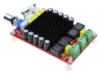
I have two of these red boards too (picture). I use them for amplifying the bass and tweeter of an active system. I have some questions on the modding.The input coupling capacitors seem to be foil, fine.
The output filter capacitors seem to be foil as well, fine.
The output filter chokes are SMD types with a peak rating (before saturation) of about 3A - not sufficient.
The power line decoupling capacitors are six 470uF/50V that offer good margins for the supply voltage but are insufficient with most power supplies for 2x100W.
A good size heatsink but you have to see if it gets above 50 degrees Celsius.
Most importantly the output filter chokes should be changed to types with a rating of minimum 8A. It may be difficult to get other and bigger chokes mounted instead of the SMD ones.
For more power supply decoupling, arrange some 5000uF-10000uF just outside of the power supply terminals.
Lastly, consider short-circuiting the protection diode (polarity protection) found in between the output filter chokes. Then your external decoupling has got more effect.
You will most likely be happy with this board.
- I intend to add a 10000 uF capacitor between power supply and the boards. This must be connected in parallal to plus and min? The power supply is connected to both amplifiers so the capacitor will work for both?
- The output filter chokes are limited to 3A. I assume this is sufficient for amplifying the tweeter?
- What are the values needed for the output filter chokes? I see offerings of 10 uH/10A, that will do? What is the largest value that doesn't affect the sound? This is related to the value of the capacitor too I guess?
- I am thinking of making these coils myself (this is a DIY forum) I have various coils used for passive filtering. What if I wind 0.7/1 mm copper wire 15 times around something, glue it so it stays together and make an aircoil in this way?
How critical are the values in the output filter? I found a document of TI with considerations and calculations on this topic http://www.ti.com/lit/an/slaa701a/slaa701a.pdf. It strikes me that class D amplifyers are modded without calculating and measuring the effect of the filter.
Another thought: If I use one amplifyer just for amplifying low frequencies why would I need an output filter for that amplifyer anyway? For the tweeter a well dimensioned filter is important but this is easy as no high power has to be digested.
Attachments
can someone spec the best bang for buck caps to use on the 1
2
also, if someone knows what inductors to purchase to change out the 330 black box smd ones on the Bluetooth board would be appreciated too! the black ones get as warm as the chip with only 19V and have ordered 24V. thanks 8 ohm speakers
I like ZLH caps for the radials and FC caps for the SMDs. Use of both have resulted in notable improvement in sound quality in every Class D amp I have used them.
- I intend to add a 10000 uF capacitor between power supply and the boards. This must be connected in parallal to plus and min?
The power supply is connected to both amplifiers so the capacitor will work for both?
Yes, 10000uF is fine. Connect in parallel to the "+" and "-" supply terminals. Just short the polarity protection diode (between the filter chokes) first and be careful with the polarity in the future. The 10000uF will work for both channels.
- The output filter chokes are limited to 3A. I assume this is sufficient for amplifying the tweeter?
- What are the values needed for the output filter chokes? I see offerings of 10 uH/10A, that will do? What is the largest value that doesn't affect the sound? This is related to the value of the capacitor too I guess?
Your "red board" is TDA7498 (and not TDA7498E which is also red but different). With 4 Ohm speakers you may have currents close to 4 Amp RMS, thus, 5-6 Amp peak. This board is sold at a very reasonable price so they saved on the chokes. At moderate sound-levels it works but with a loud level and a bass transient you may hear the limit being reached. It is difficult to unsolder the chokes with the little free space on this board but if you manage, look for some with a 7-8 Amp rating. Unfortunately, 7-8 Amp chokes are significantly larger so they may have to "fly" above. With 8 Ohm speakers you have half the current so the problem is less (TDA7498 seems intended for 6 or 8 Ohm).
You write "what is the largest value that doesn't affect the sound" - I believe you mean what is the smallest (current) rating that doesn't affect the sound? Depending on if you use 4 or 8 Ohm speakers, you may have currents up to 4 Amp RMS. That means up to almost 6 Amp peak. The more you run a choke close to its saturation point, the more you affect the sound. Generally, the more margin the better but be pragmatic.
- I am thinking of making these coils myself (this is a DIY forum) I have various coils used for passive filtering. What if I wind 0.7/1 mm copper wire 15 times around something, glue it so it stays together and make an aircoil in this way?
How critical are the values in the output filter? I found a document of TI with considerations and calculations on this topic http://www.ti.com/lit/an/slaa701a/slaa701a.pdf. It strikes me that class D amplifyers are modded without calculating and measuring the effect of the filter.
The output filter chokes are typically 15uH or 22uH. Implementing that as air-coils will require a lot of windings, and with an 1.0-1.3 mm wire diameter the air-coils will just be huge. Next, air-coils are good antennas and a huge coil with more amperes at 300KHz-400KHz will cause a lot of disturbance. In theory air-coils are fine (no saturation) but in praxis NO (for that use).
The filter precision is not so important simply because it serves to recover the average value of a PWM squarewave signal. Often, a cut-off frequency around 40KHz is chosen, but 35KHz to 50KHz will do as well. The saturation current is the most ignored parameter. The choke value should be chosen to match the damping from the speaker (typically 22uH for 8 Ohm and 10-15uH for 4 Ohm).
Another thought: If I use one amplifyer just for amplifying low frequencies why would I need an output filter for that amplifyer anyway? For the tweeter a well dimensioned filter is important but this is easy as no high power has to be digested.
NO, NO, if you mean the amplifier output filter. The filter is not a filter in the audio range, it works on frequencies above the audio range. Class D works such that your nice low-power audio signal is Pulse Width Modulated (PWM) into a low power PWM (square-wave) signal. The PWM signal is amplified to a much higher amplitude (still square-wave) and then the output filter at the end recovers the average of the PWM signal. The average of the PWM signal is your audio signal but amplified.
If you did not use an output filter, you would try to send your PWM signal directly to the speaker which could harm both speaker and amplifier (some nasty current spikes). For some low power class D chips (TPA3110, PAM8403, PAM8610, YDA38E) they manage without an output filter, but that is due to the low power and relying on the speaker cable providing a minimum of inductance.
Filter-less TDA7498 - not a good idea. The more power, the worse.
Last edited:
Hi @FauxFrench, I see from your detailed explanations that you have a vast experience with these TDA7498 boards; could you reccomend me some version of these boards which I could just fire up with minimal tweakings and it is currently available on ebay and could optimally use with some 4 ohm speakers?
I was reading on this webpage that for 4 ohm load I must be changing the output inductors to 15 uH or ideally to 10uH, I am fine with that also
Trevor Marshall - Class D Audio Amplifier Design - TDA7498 Output filters
I am just needing to be pointed to an adecvate TDA7498 for my 4 ohm needs; another question, would TDA7498E version better suit my needs, or is just for more power? I have a 24V (360W) SMPS that can be tuned up to 30V
thanks in advance
chokes and coils
I found out that the 220 number on the SMD coils refers to 22 uF. Air coils of these values are sold by Jantzen http://www.jantzen-audio.com/wp-content/uploads/2013/04/Air-Core-Wire-Coils-Values-17.11.2017.pdf Apparently aircoils give high frequent radiation. Can I solve this by packing them in aluminium foil?
Jantzen doesn't recommend toroidal coils for the higher range. Toroidal coils/chokes in the range of 8-10A are quite scarse and expensive.
Thanks for your elaborate answer. It strikes me that these output filters are delivered with poor components while people spend high amounts on expensive components in their passive filters. Especially in the bass range the difference is hugh: compare the wax, cross and litz coils with the small smd coils that precede in class D amplifiers in the signal path.The output filter chokes are typically 15uH or 22uH. Implementing that as air-coils will require a lot of windings, and with an 1.0-1.3 mm wire diameter the air-coils will just be huge. Next, air-coils are good antennas and a huge coil with more amperes at 300KHz-400KHz will cause a lot of disturbance. In theory air-coils are fine (no saturation) but in praxis NO (for that use).
The filter precision is not so important simply because it serves to recover the average value of a PWM squarewave signal. Often, a cut-off frequency around 40KHz is chosen, but 35KHz to 50KHz will do as well. The saturation current is the most ignored parameter. The choke value should be chosen to match the damping from the speaker (typically 22uH for 8 Ohm and 10-15uH for 4 Ohm).
I found out that the 220 number on the SMD coils refers to 22 uF. Air coils of these values are sold by Jantzen http://www.jantzen-audio.com/wp-content/uploads/2013/04/Air-Core-Wire-Coils-Values-17.11.2017.pdf Apparently aircoils give high frequent radiation. Can I solve this by packing them in aluminium foil?
Jantzen doesn't recommend toroidal coils for the higher range. Toroidal coils/chokes in the range of 8-10A are quite scarse and expensive.
First, I have to admit I buy my boards directly from the far east at the lowest price I find. Taking the price into account, all the boards (more than 20) I have bought have been worth the money. Only one very cheap board (TDA7293) needed immediate repair as the IC was defect. Some board implementations I would have made differently but then I buy a cheap board as a starting point and modify it myself.
TDA7498 is also found as TDA7498E and there are some important differences. From the datasheets we can learn a lot:
TDA7498: 39V max. supply voltage, over-current protection at 7 Amp., 200mOhm output switches, THD 0.1%, specified for 6 and 8 Ohm loads.
TDA7498E: 39V max. supply voltage, over-current protection at 11 Amp., 150mOhm output switches, THD 0.05%, specified for down to 3 Ohm loads.
First impression, the TDA7498E is more powerful with 4 (or 3) Ohm loads as it can handle more current and the output switches have less impedance. The TDA7498E has even a lower THD which is supported by Fig.6 of the datasheet.
Price difference:
TDA7498 2x100W Digital Power Amplifier Board Audio Amplifier Class D Dual Audio Stereo DC 14 34V For Home Theater Active Speaker-in Amplifier from Consumer Electronics on Aliexpress.com | Alibaba Group
1pc 2 Channel TDA7498E Digital Audio Amplifier High Power Amplifier Board Module 4/6/8ohm-in Amplifier from Consumer Electronics on Aliexpress.com | Alibaba Group
Thus, a TDA7498 board costs about half of a TDA7498E board.
I only have the TDA7498E board mentioned above and I am very happy with it. I did no modifications on it apart from short-circuiting the two polarity protection diodes. I use 10000uF as extra power decoupling on the power input terminals. I find it a very good board for all kind of use and very well implemented for such a low price. It can easily pull 4 Ohm loads.
The TDA7498 board is very good value for money though savings have been made on the output filter chokes. Half the price means some savings. The TDA7498 is fine for 8 Ohm loads but less suited for 4 Ohm loads.
If an 8 Ohm load is used, both boards can deliver the same output power as they are both limited by the maximum supply voltage of 39V. But, the TDA7498E seems to have a slight advantage in a lower THD, better output filter and a better heatsink.
As a purely subjective choice, I prefer the TDA7498E board but both are really “value for money”.
Last edited:
Thanks for your elaborate answer. It strikes me that these output filters are delivered with poor components while people spend high amounts on expensive components in their passive filters. Especially in the bass range the difference is hugh: compare the wax, cross and litz coils with the small smd coils that precede in class D amplifiers in the signal path.
I found out that the 220 number on the SMD coils refers to 22 uF. Air coils of these values are sold by Jantzen http://www.jantzen-audio.com/wp-content/uploads/2013/04/Air-Core-Wire-Coils-Values-17.11.2017.pdf Apparently aircoils give high frequent radiation. Can I solve this by packing them in aluminium foil?
Jantzen doesn't recommend toroidal coils for the higher range. Toroidal coils/chokes in the range of 8-10A are quite scarse and expensive.
Air coils is something I relate to passive speaker filters (low impedances and no saturation) where the frequencies are up to 20KHz such that radiation is less a of a problem. And, from old radio receivers where ferrite handling HF frequencies well was difficult to find.
Looking at the cheap amplifier modules, in particular I buy, they cost from 1 EUR to 20 EUR (I recently bought a TDA3255 board at 42 EUR as an exception). You can imagine what can be produced in your country for max. 20 EUR? The amplifier modules we buy (origin probably always from far east) are terribly cheap (we cannot compete with such prices). But, to sell at such prices, also out there (east) they need to save on anything they can.
Then, we put this max. 20 EUR amplifier on our speakers that cost several hundreds of Euro. Not necessarily a balanced spending on the system components. Therefore, only spend very good chokes on amplifiers where the other amplifier components deserve really good chokes. Buy cheap amplifiers for experiments and gain of knowledge and eventually put better chokes in temporarily - if the amplifier is destroyed during the experiments, OK it was cheap and the best components are recovered for the next project.
1pc 2 Channel TDA7498E Digital Audio Amplifier High Power Amplifier Board Module 4/6/8ohm-in Amplifier from Consumer Electronics on Aliexpress.com | Alibaba Group
Thus, a TDA7498 board costs about half of a TDA7498E board.
I only have the TDA7498E board mentioned above and I am very happy with it. I did no modifications on it apart from short-circuiting the two polarity protection diodes.
thanks for clarifying, one friend bought a supposedly TDA7498E board like this in your link but together with an aluminium enclosure; the chip fried after some experiments and after taking out the heatsink he found out that the chinese supplier sold him a plain TDA7498 without "E"; after this he ordered a genuine "e" chip from mouser and now he is happy with it; did you had the curiosity to look under that heat sink?
also, do you happen to know what value are those chokes on the output? are they in the 10-15 uH range to be suitable for 4 ohm loads or would I have to buy other ones?
I found these 2 options on ebay, maybe you can take a look
Coilcraft DO5010H-123ML 12uH inductor Irms=5.2A, Isat=8.5A, 28milliohms | eBay
5pcs 10uH 7.5A Small Toroidal Inductor Magnet inductance Coil Anti-Interference | eBay
I connected the capacitor without shorting the polarity diode. Why do I need to short this?Yes, 10000uF is fine. Connect in parallel to the "+" and "-" supply terminals. Just short the polarity protection diode (between the filter chokes) first and be careful with the polarity in the future. The 10000uF will work for both channels.
I agree with your observations of the balance between expensive speakers and cheap amplifier. At the other hand I think most of these amplifiers are not balanced as well as the quality of the chip in many cases is better than the rest of the board.Air coils is something I relate to passive speaker filters (low impedances and no saturation) where the frequencies are up to 20KHz such that radiation is less a of a problem. And, from old radio receivers where ferrite handling HF frequencies well was difficult to find.
Looking at the cheap amplifier modules, in particular I buy, they cost from 1 EUR to 20 EUR (I recently bought a TDA3255 board at 42 EUR as an exception). You can imagine what can be produced in your country for max. 20 EUR? The amplifier modules we buy (origin probably always from far east) are terribly cheap (we cannot compete with such prices). But, to sell at such prices, also out there (east) they need to save on anything they can.
Then, we put this max. 20 EUR amplifier on our speakers that cost several hundreds of Euro. Not necessarily a balanced spending on the system components. Therefore, only spend very good chokes on amplifiers where the other amplifier components deserve really good chokes. Buy cheap amplifiers for experiments and gain of knowledge and eventually put better chokes in temporarily - if the amplifier is destroyed during the experiments, OK it was cheap and the best components are recovered for the next project.
Buying these cheap boards is somehow addictive the more I know of it, although I have some failing ones you are aware of.
The 7498E board with fan you discussed in your former post has good chokes, but the capacitors to me seem very small. Are these folie capacitors? The pp capacitors I use for crossover filters are larger.
- Status
- Not open for further replies.
- Home
- Amplifiers
- Class D
- Ebay cheap TDA7498 boards