Hi
Charles,
So dead time adjusting will be dangerous depending from dVin/dt and + more nonlinearity.
How your weekend class D practice? About my UcD_like practicing:seem THD from 0.05 to 0.01% isn't affect the sound tranparency,the sound very clear but i don't know why... just blur free (thx to subwo1 for this term "doesn't blur the image")")
Charles,
So dead time adjusting will be dangerous depending from dVin/dt and + more nonlinearity.
How your weekend class D practice? About my UcD_like practicing:seem THD from 0.05 to 0.01% isn't affect the sound tranparency,the sound very clear but i don't know why... just blur free (thx to subwo1 for this term "doesn't blur the image")
Class D amp
Just wondering what sort of switching frequency have you managed to get?
What sort of efficiency are u getting amp man? I have tried before making a class d amplifier had lot of trouble tring to get the high frequency (RF) switching component out of the audio.. The filter seemed to require large inductors and had many stages..I was never happy with the sound quality. so I gave up?
I have used in the passed little ferrite coupling transformers instead of high side switches as I had found I could get more gate drive and got isolation also, this way I managed to get the gates of the mosfets to switch on and off when I wanted them to meaning less dead band was required! gate capacitance can be a hastle. so is the nasty high voltage kick back spikes you get when switching into an inductive load example dc-to-dc converters!
cheers,
Bevan.
So dead time adjusting will be dangerous depending from dVin/dt and + more nonlinearity.
How do you get to this conclusion ? IMO it doesn't matter how you introduce dead-time. But maybe there is something that I have overlooked.
How your weekend class D practice?
Unfortunately things never go as planned. This was meant to be a calm week and a calm weekend with my GF being absent. Quite the contrary was the case ! Instead of beeing away for ski holidays she made a skiing accident during the weekend so that I can look after her now !
Regards
Charles
Hi Charles,
So dead time adjusting will be dangerous depending from dVin/dt and + more nonlinearity.
How your weekend class D practice? About my UcD_like practicing:seem THD from 0.05 to 0.01% isn't affect the sound tranparency,the sound very clear but i don't know why... just blur free (thx to subwo1 for this term "doesn't blur the image")
Hi Charles. I think that if the audio input is only 10uV, for example, the threshold for the second comparator may not be crossed and distortion would be high. It should be best keeping dead time right before mosfet drive.
I regret that you were not as free as you hoped last weekend as I too was anxious to find out how you class D project was proceeding.
Thanks Ivan. I picture the input signal being mixed with a delayed feedback signal as causing distortion. Maybe it would be IMD, but I just think it wouldn't be a good thing.
Hi Charles. I think that if the audio input is only 10uV, for example, the threshold for the second comparator may not be crossed and distortion would be high.
I see what you mean, but don't forget that the audio is always "riding" on the triangle. Even a 1 nV (O.K. this is alittle exagerated and will also be below noise level ....) signal will therefore proportionally influence the duty cycle.
I though see that dead-time in general will give rise to distortion since every timing-error that is introduced will affect linearity. But it will not be the same as the crossover distortion of a class B amp as some sources claim.
amp_man_1:
If you need a single comparator that has two outputs, that are out of phase, then look at the LM361 which is a really damnboodycool device, though a little expensive.
Regards
Charles
Commentable Thoughts
Mr. Charles ThanX for great advice.
The LM361 is indeed DIFFERENTIAL INPUT AND DIFFERENTIAL OUTPUT COMPARATOR will it perform good??
So do u think that using 2 LM319 comparators will create problems??
Regards
Ampman
phase_accurate said:
amp_man_1:
If you need a single comparator that has two outputs, that are out of phase, then look at the LM361 which is a really damnboodycool device, though a little expensive.
Regards
Charles
Mr. Charles ThanX for great advice.
The LM361 is indeed DIFFERENTIAL INPUT AND DIFFERENTIAL OUTPUT COMPARATOR will it perform good??
So do u think that using 2 LM319 comparators will create problems??
Regards
Ampman
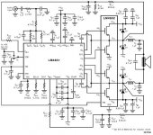
I have a question about another Class D amp,as you seems to know what youre talking about.It is with LM4651-LM4652,as in the schema,is it possible to paralell more LM4652 modules for more output power.Or do you know of any other DIY Class D amp,
with outpup power of 300w or more for driving a Sub woofer?
http://www.national.com/pf/LM/LM4651.html
with outpup power of 300w or more for driving a Sub woofer?
http://www.national.com/pf/LM/LM4651.html
Attachments
hi.
>as you seems to know what youre talking about> , who??
do you mean 300w into 4 ohms? rms or peak?
you can use higher power fets with the driver and get more power , do you want to make your own layout?
if youre not familiar with design and layout of pwm amplifiers another good option would be to buy a finished amp or module.
rgds karsten madsen - www.cadaudio.dk
But it will not be the same as the crossover distortion of a class B amp as some sources claim.
When I built my first experimental class D amp over 15 years ago, I tried converting a linear amp to D. It was quite awful.

I mean 300 or more rms.I am not so familiar with design and layout of pwm amp.But I know theres a evolution board for thisdo you mean 300w into 4 ohms? rms or peak?
design to buy,and I am not afraid of experimenting to see if it works.So its not a god idea to paralell more LM4562´s as they are modules,that put out 170W/4 Ohm-10% dist.I already have a transformer 2x30Volts that I is possible to use with this design,but I need more output power.That´s why I thougt of paraleeling,or could you suggest any higher power fets and how to connect them-to get 300w or more rms.By the way I thougt the LM4561/62 where quite cheap.On cadaudio it says Class-T amplifier is it the same as class D?
ryssen said:I found out from the national website´s FAQ that it is possible to
connect 2 modules in paralell,maybee i´ll try with 3 modules.Anyway how critical is the lenght of the wires to use from the board to the modules,if I use say 3cm wires,will there be any side effects?
first of all... a 2 X 30volt transformer is too high voltage rails for this amp, and second, paralleling output ICs will only enable you to drive lower impedences...
/
http://www.cadaudio.dk and they have some nice amp´s,but I thougt they where quite expensive,compared to this other Ic´s from National I was talking about,and as I am from Sweden there is VAT and moms (dont know what that is in English) Shipping on the price.Plus the components are already solderd on the board(I´d like to solder my self).
Anyone know of some DIY kit or where to get a board (I could by the components in Sweden)
Gonna do some searching my self,just thought if anyone knew?
Ok,I thougt if I used regulators to get the volt down,I went toa 2 X 30volt transformer is too high voltage rails for this amp, and second, paralleling output ICs will only enable you to drive lower impedences...
http://www.cadaudio.dk and they have some nice amp´s,but I thougt they where quite expensive,compared to this other Ic´s from National I was talking about,and as I am from Sweden there is VAT and moms (dont know what that is in English) Shipping on the price.Plus the components are already solderd on the board(I´d like to solder my self).
Anyone know of some DIY kit or where to get a board (I could by the components in Sweden)
Gonna do some searching my self,just thought if anyone knew?
Class-D Amp with Discrete Gate Drivers
Let me tell you guys that as someone who has fixed his fair share of class D amplifiers, not to discourage any interest ,and had the chance to audition many of these designs, after the repair of course, that they suck.
They dont exactely control the woofers excursion too good. Sometimes with a sudden squaring of the audio signal delivered to the speaker, that results in a large thump.( Most likely caused by the PWM pulse width maxing out ), on large dynamics.

- Status
- This old topic is closed. If you want to reopen this topic, contact a moderator using the "Report Post" button.
- Home
- Amplifiers
- Class D
- Class-D Amp with Discrete Gate Drivers