Hi,
I have a pair of UCD400OEM's and UCD700OEM's. I'm going to build two fully dual mono amps out of those. I'll build linear power supplies for those.
In both ucd400oem and ucd700oem there is a quite similar DC-error detection circuitry. ucd700oem spec says:
Now, my question is that does anyone have the dc-protection circuit diagram for any of the Hypex linear power supplies, such as these:
Can I feed this DC-Error detection output from the ucd-module directly just to switch the relay contacts off? Or does it require any additional circuitry.
I know that there is some guy who used this kind of circuitry with ucd180ad-modules:
To me, that looks overkill for ucd400 and ucd700. Am I right?
So, how should I implement the rail voltage shutt-off using DC-error output from the amp-modules with relays in PSU?
I have a pair of UCD400OEM's and UCD700OEM's. I'm going to build two fully dual mono amps out of those. I'll build linear power supplies for those.
In both ucd400oem and ucd700oem there is a quite similar DC-error detection circuitry. ucd700oem spec says:
DC-Error Detection Characteristics
The UcD700™ (OEM version) has an integrated DC-error detection which will pull pin J10:1 low in case of such an event. It is recommended to sense this fault condition and to interrupt both power supply lines in such an event.
Item: Voltage on pin J10:1, DC-error
Max: 1V
Notes:
* Internal open collector
* Must be pulled to a positive voltage by means of an external resistor. Open collector maximum output current: 100mA. Maximum collector voltage: 150V.
Now, my question is that does anyone have the dc-protection circuit diagram for any of the Hypex linear power supplies, such as these:
HYPEX UCD 700 HG POWER SUPPLY 700 WATT | hifisound.de | purchase online
Strassacker: Speaker Building, Components
Strassacker: Speaker Building, Components
Can I feed this DC-Error detection output from the ucd-module directly just to switch the relay contacts off? Or does it require any additional circuitry.
I know that there is some guy who used this kind of circuitry with ucd180ad-modules:
To me, that looks overkill for ucd400 and ucd700. Am I right?
So, how should I implement the rail voltage shutt-off using DC-error output from the amp-modules with relays in PSU?
Underkill !
The used Finder relays in the schematic have a max breaking DC current of 2.5 Amps at 45 Volts DC ( from Finder datasheet ) with a 4 ohm speaker at DC failure that current would be in the order of 11.5 amps and with 8 ohm speakers about half of that . So good luck with that solution
IMO better to go with a FET switch solution , something like this :
A DC Fault Protection Circuit for Audio Amplifiers
The second schematic , Just connect the LED in the PV to your protection active low on the UCD and the other side with a resistor to positive rail .
Cheers ,
Rens
Hi,
http://home.kabelfoon.nl/~dezaire/UcD180AD/UcD180AD_8.jpgTo me, that looks overkill for ucd400 and ucd700. Am I right?
So, how should I implement the rail voltage shutt-off using DC-error output from the amp-modules with relays in PSU?
The used Finder relays in the schematic have a max breaking DC current of 2.5 Amps at 45 Volts DC ( from Finder datasheet ) with a 4 ohm speaker at DC failure that current would be in the order of 11.5 amps and with 8 ohm speakers about half of that . So good luck with that solution
IMO better to go with a FET switch solution , something like this :
A DC Fault Protection Circuit for Audio Amplifiers
The second schematic , Just connect the LED in the PV to your protection active low on the UCD and the other side with a resistor to positive rail .
Cheers ,
Rens
Last edited:
Looks interesting and just as simple as I was hoping for..
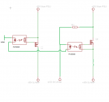
Do you mean like this:
https://www.dropbox.com/s/9wh08pqrbv08utv/DC-Error.PNG
The second schematic , Just connect the LED in the PV to your protection active low on the UCD and the other side with a resistor to positive rail .
https://www.dropbox.com/s/9wh08pqrbv08utv/DC-Error.PNG
Last edited:
Looks interesting and just as simple as I was hoping for..
Do you mean like this:
https://www.dropbox.com/s/9wh08pqrbv08utv/DC-Error.PNG
I made a mistake Oops , come back later have to go now , Your schematic will not work . You have to invert the logic low on DC error to logic high and vice versa , but still very simple .You'll need a photovoltaic FET driver , not an optocoupler The third schematic in my example will work with logic low on DC error .
Catch you later
Cheers ,
Rens
Last edited:
Looks interesting and just as simple as I was hoping for..
This should work .
The PV is a double one so you need only one or use two with the inputs and outputs in series if you need more voltage for the FETs .
The series resistor need to privide around 10mA through the Led's so around 8kohm and minimum 1 Watt . If the DC protect goes Low , the Led's are shorted and the FET's close .
Note that the circuit is not latching so the fault will repeat itself over and over ,
The latching can be done with a simple micro controller or a small relay .
Good luck !
Cheers ,
Rens
Attachments
OK, thanks!
As you already probably noticed, I am not an electronics engineer and I might ask some stupid questions
One thing that I don't understand is what does it mean when dc-error on ucd goes low and what does the 1V mean in the spec. Does it mean that when everything is ok, then it outputs 1V and when dc error exists it shorts to ground or vice versa? Or does it mean that when everything is ok it is not connected in any way and in case of dc error it shorts to ground?
Therefore, I don't understand why in your schematic the dc-error is connected to the pv on the resistor side. To me it looks like the resistor is going to explode when dc-error shorts to ground...
Therefore, why wouldn't this work?

As you already probably noticed, I am not an electronics engineer and I might ask some stupid questions
One thing that I don't understand is what does it mean when dc-error on ucd goes low and what does the 1V mean in the spec. Does it mean that when everything is ok, then it outputs 1V and when dc error exists it shorts to ground or vice versa? Or does it mean that when everything is ok it is not connected in any way and in case of dc error it shorts to ground?
Therefore, I don't understand why in your schematic the dc-error is connected to the pv on the resistor side. To me it looks like the resistor is going to explode
when dc-error shorts to ground...Therefore, why wouldn't this work?
How much is the on-state resistance of the FET? Will it become a limiting factor? Piisami: any specific reason to waht to do a linear supply instead of using the standard hypex SMPS?IMO better to go with a FET switch solution
How much is the on-state resistance of the FET? Will it become a limiting factor? Piisami: any specific reason to waht to do a linear supply instead of using the standard hypex SMPS?
Well , that was also my next question . If you didn't buy any power supply yet , why not buy a SMPS with build in protection like the Hypex or the new Connexelectronic ones .
About the Rds on of the FET's I'm not to worried , even a cheap 150V one with say 50 mohms will only dissipate 0.5 watt with 10 Amps of current , so wont need any heatsink .
Piisami ,
Your schematic won't work , because the DC protect will never go low ( 0 Volt) the FETs wont get open .
The resistor in my schematic will not blow when the DC error signal gets to ground , because there's 85 volts over a 8kohm resistor and the current through the resistor is only 85/8 = 10.6 mA and the power in the resistor will be 10.6 x 85 = 900 mW
all these figures are well in the Hypex specs as you provided :
Item: Voltage on pin J10:1, DC-error
Max: 1V
Notes:
* Internal open collector
* Must be pulled to a positive voltage by means of an external resistor. Open collector maximum output current: 100mA. Maximum collector voltage: 150V.
the 1 V mentioned in the specs means that's the max voltage drop over the transistor in the Hypex UCD module when the transistor is in the OPEN state on a DC error and shorts to ground .
If everything is OK the transistor is closed and acts like an infinite resistor and the current flows through the LED's in the Photovoltaic FET drivers and force them in the OPEN state .
Don't worry about any stupid questions , that's what this forum is all about to help each other out and get wiser from each others knowledge !
Cheers ,
Rens
Last edited:
Agree, the power dissipation is not an issue - but one of the strong points of the Hypex modules is the low output impedance (the UcD400OEM is specified as 20 mohm below 1 kHz). Won't the 50 mohm Rds compromise that?About the Rds on of the FET's I'm not to worried , even a cheap 150V one with say 50 mohms will only dissipate 0.5 watt with 10 Amps of current , so wont need any heatsink.
Agree, the power dissipation is not an issue - but one of the strong points of the Hypex modules is the low output impedance (the UcD400OEM is specified as 20 mohm below 1 kHz). Won't the 50 mohm Rds compromise that?
It will have some effect , but I think the output impedance is mainly set by the DC resistance of the output inductor and the Rds on of the output FETS , but I'm getting on thin ice here
If I would use the schematic myself I would go for FET's with the lowest possible Rds on , but it's going to cost you a much higher gate charge and longer switching times , although I think this won't matter much in this application .
Cheers ,
Rens
But aren't the protection FETs in series with the output FETs? So it all adds up...It will have some effect , but I think the output impedance is mainly set by the DC resistance of the output inductor and the Rds on of the output FETS
But aren't the protection FETs in series with the output FETs? So it all adds up...
I agree , but not having seen the UCD modules schematics I assume they have some serious rail buffering on Board , so that would greatly reduce the effect of the protection FET's resistance .
That's the greatest disadvantage of protection ! You always give in on performance ! unless you go for a crowbar
IMHO I think the fast shutdown gives the least performance reduction and is the most reliable of all forms of DC protection .
Cheers ,
Rens
True.I assume they have some serious rail buffering on Board , so that would greatly reduce the effect of the protection FET's resistance.
Only with a linear supply. With a SMPS that has switching elements anyway, you can do the protection as part of the control circuitry, without any downsides.That's the greatest disadvantage of protection ! You always give in on performance!
Piisami: any specific reason to waht to do a linear supply instead of using the standard hypex SMPS?
That is just my personal preference, I have always liked linear psu better when done right. Also, I have plenty of big trafos and caps on hand.
Fair enough - personal choice is personal choice. But as indicated, you are giving away some real benefits. It is my experience that a well-designed, synchronous SMPS (such as the hypex one) works much better with the hypex modules than a linear supply. OK, my experience is with the nCore modules, but...That is just my personal preference, I have always liked linear psu better when done right. Also, I have plenty of big trafos and caps on hand.
OK, I think I've got it, thanks!Your schematic won't work , because the DC protect will never go low ( 0 Volt) the FETs wont get open .
The resistor in my schematic will not blow when the DC error signal gets to ground , because there's 85 volts over a 8kohm resistor and the current through the resistor is only 85/8 = 10.6 mA and the power in the resistor will be 10.6 x 85 = 900 mW
all these figures are well in the Hypex specs as you provided :
Item: Voltage on pin J10:1, DC-error
Max: 1V
Notes:
* Internal open collector
* Must be pulled to a positive voltage by means of an external resistor. Open collector maximum output current: 100mA. Maximum collector voltage: 150V.
the 1 V mentioned in the specs means that's the max voltage drop over the transistor in the Hypex UCD module when the transistor is in the OPEN state on a DC error and shorts to ground .
If everything is OK the transistor is closed and acts like an infinite resistor and the current flows through the LED's in the Photovoltaic FET drivers and force them in the OPEN state .
With a SMPS that has switching elements anyway, you can do the protection as part of the control circuitry, without any downsides.
Totally agree
"IMHO I think the fast shutdown gives the least performance reduction and is the most reliable of all forms of DC protection ."
ordered this one some time ago : Connexelectronic
Only downside is that secondary capacitors still discharge into your speakers on DC error ( not good in active systems mids and highs )
No worries Piisami the protection will work with the right FET's and PVI's and preferable a latch on a DC error . I have some spare time tomorrow and have a look at suitable FET's and a latch circuit . I made some nice protection circuits with a Picaxe 08M .Are you familiar with those chips ? If not I can program them and post it to you . They are only 3 dollars or so each .
I don't think the PSU protection will downgrade the sound quality of your amps .
It would be measurable but only with very accurate equipment .
Cheers ,
Rens
Last edited:
No worries Piisami the protection will work with the right FET's and PVI's and preferable a latch on a DC error . I have some spare time tomorrow and have a look at suitable FET's and a latch circuit . I made some nice protection circuits with a Picaxe 08M .Are you familiar with those chips ? If not I can program them and post it to you . They are only 3 dollars or so each .
I don't think the PSU protection will downgrade the sound quality of your amps .
It would be measurable but only with very accurate equipment .
I have heard of those chips but never tried one. Back in the days I programmed some PIC and Atmel chips, though.
I'm going to design a PCB for this project including rectifier diodes, caps, snubbers, dc-protection, etc (and probably auto-on) and share it here. In the end, I'll manufacture small quantity of pcbs (10 or so, I'll need 4 by myself). I have a very good experience with a Chinese manufacturer, specialised on small quantities for hobbyists with reasonable pricing. I will let you know later..
I'm very interested on readily programmed chips
.I could send you some PCBs afterwards, if interested..Anyway, I was thinking to parallel two or more FETs, this would make more choice for FETs and, to my knowledge, lower the FET resistance.
Could VOM1271 be used here, it would be easier to source? Even google can't find the PVI5030
BR, Sami
I have heard of those chips but never tried one. Back in the days I programmed some PIC and Atmel chips, though.
I'm going to design a PCB for this project including rectifier diodes, caps, snubbers, dc-protection, etc (and probably auto-on) and share it here. In the end, I'll manufacture small quantity of pcbs (10 or so, I'll need 4 by myself). I have a very good experience with a Chinese manufacturer, specialised on small quantities for hobbyists with reasonable pricing. I will let you know later..
I'm very interested on readily programmed chips
Anyway, I was thinking to parallel two or more FETs, this would make more choice for FETs and, to my knowledge, lower the FET resistance.
Could VOM1271 be used here, it would be easier to source? Even google can't find the PVI5030
BR, Sami
VOM1271 looks good , much faster as PVI5013 ( sorry for the typo ) , was just an indication , paralleling FETs is a good idea , but there are some pretty low resistance ones out there , come back later , bed time here in Australia !
One more question , do you have any lower voltage available for the PIC .
Would save some power resistors and zeners in the design.
Cheers ,
Rens
One more question , do you have any lower voltage available for the PIC .
Would save some power resistors and zeners in the design.
Yes, I can steal it from 2x13Vac buffer PSU trafo and requlate to lower voltage.
- Status
- This old topic is closed. If you want to reopen this topic, contact a moderator using the "Report Post" button.
- Home
- Amplifiers
- Class D
- Hypex Linear PSU DC-error protection