D
Deleted member 148505
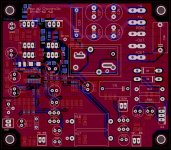
I updated freebie gerber for liteamp.
Compatible inductors:
AGP2923 / VER2923
1D31A
1D23A
T157-2 (vertical mount DIY)
Can use IPP120N20NFD
Chassis mount resistor for zobel
Heatsink mounting should look like the one attached (see prototype)
Attached schem (just don't mind the component values)
If anyone wants the gerber, please message me
Attachments
 looks like was nice this Xmas and brought a decent scope..
Hi guys,
I'm about to quit this project.
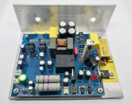
I got 3 boards, SMD and trough-components are soldered on, they just need to be tested according to Choco's guide and then the last parts can be soldered on. I got all parts for them to be completed
I got a 300VA 2x28VAC toroid for each board with capacitors, and resistors. I planned to make a CRCC PSU with a bleeder resistor.
PM me anyone if any of you are interested to buy it..
I can reply with the orders from Digikey and Reichardt, so you can see what you get")
BR
Per.
I'm about to quit this project.
I got 3 boards, SMD and trough-components are soldered on, they just need to be tested according to Choco's guide and then the last parts can be soldered on. I got all parts for them to be completed
I got a 300VA 2x28VAC toroid for each board with capacitors, and resistors. I planned to make a CRCC PSU with a bleeder resistor.
PM me anyone if any of you are interested to buy it..
I can reply with the orders from Digikey and Reichardt, so you can see what you get
BR
Per.
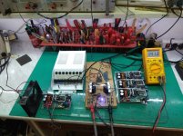
First board tested with +-70V DC power supply, sound is very good ,no hum or noise .3 more boards ready for testing with higher supply,for now they were tested only with +-40Vdc.
Not the easiest amp to assembly but it is worth to try.
Thanks ChocoHolic for sharing your amp .
regards
Zoky2
Not the easiest amp to assembly but it is worth to try.
Thanks ChocoHolic for sharing your amp .
regards
Zoky2
Attachments
It always makes me happy to see new builds. My congratulation.
====================================================
One general remark. From theory it is not mandatory:
But after touching Q1 of my 2x80V version, my bio sensor convinced
me to put a small heat sink for Q1 as well.
Note: You must not touch it anyhow, because of dangerous voltage!
The gap between theory and bio sensor feedback is clear:
Bio sensors send alarm above 65 C, while such BJTs can easily run reliably for long term above 100C. Likely the heat sink for Q1 is just cosmetic, but I felt better after putting it.
Last edited:
D
Deleted member 148505
hi all , jlester any updates
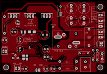
Planning to sell 500w version on my eBay page.
Board size 65 x 95mm
Attachments
Hi Jlester,
Greetings, can you give me inductors lib file (EAGLE)
Regards
MANOJ
Greetings, can you give me inductors lib file (EAGLE)
Compatible inductors:
AGP2923 / VER2923
1D31A
1D23A
T157-2 (vertical mount DIY)
Regards
MANOJ
Planning to sell 500w version on my eBay page.
Board size 65 x 95mm
very cool, is it discreet 100wts without gdt ir ic?
D
Deleted member 148505
Hi Jlester,
Greetings, can you give me inductors lib file (EAGLE)
Regards
MANOJ
I created it using library editor. Attached the exported library. Opens with EAGLE 6.3.0
Attachments
I created it using library editor. Attached the exported library. Opens with EAGLE 6.3.0
hi jlester where can i buy the inductor ? what amps is it?? what is the inductance ? and what load can it carry??
Hi,I created it using library editor. Attached the exported library. Opens with EAGLE 6.3.0
Its not work for me my ver. 6.5.0
Regards
MANOJ
Its been quiet here lately,
but i guess it's a good thing, means Amps are working.
Which is why i write.
Just wanted to say that it's been a whole summer that I listened mainly through the liteamp in my system, and i am quite impressed, if I compare it to my old faithful Onkyo i am not missing anything, only compared to my valve amp there is a difference in vocal reproduction.
The liteamp is a great design and i can only recommend building it.
I would have not managed to put it together without the extensive help of Choco, i admire your patience with noobs like me
There was smoke, a faulty diode, a blown power supply and a dying analog scope on the way, but in the end it was all worth it
I just took my basic setup apart and will fit it in a old Tuner-chassis, together with the volume control and a crossover to put the amp to its final use, powering the woofers in my system...
cant wait to clean up the living room..
Thanks again!
J
but i guess it's a good thing
, means Amps are working. Which is why i write.
Just wanted to say that it's been a whole summer that I listened mainly through the liteamp in my system, and i am quite impressed, if I compare it to my old faithful Onkyo i am not missing anything, only compared to my valve amp there is a difference in vocal reproduction.
The liteamp is a great design and i can only recommend building it.
I would have not managed to put it together without the extensive help of Choco, i admire your patience with noobs like me
There was smoke, a faulty diode, a blown power supply and a dying analog scope on the way, but in the end it was all worth it
I just took my basic setup apart and will fit it in a old Tuner-chassis, together with the volume control and a crossover to put the amp to its final use, powering the woofers in my system...
cant wait to clean up the living room..
Thanks again!
J
Using the amp in my system
Hello!
i successfully transfered all the organs into the new body,
a kenwood tuner case.
liteamp - stereoscope
i got rid of some ground loop problems but i got an issue with a plopping sound when switching of the amp.
I dont want to clog up this thread because i think the problem is caused by the xover so i put it in my own thread,
but mayby one of you guys could help me out here...
Here is the link:
https://www.diyaudio.com/forums/class-d/311554-class-amp-bi-amping-woofer-3-a.html#post5665490
Happy new year!
J
I managed to destroy my module with excessive bus pumping. dc almost took out my peerless XXLS-P835017.
It seems this project is due for an upgrade. I need something for a subwoofer application.
- IRS2452AM full bridge.
- ZXGD3005E6TA mosfet drive.
- IRFB4615PBF or keep IRFI4020H.
- Assembly + maintenance friendly PCB layout. (4 layer)
- Microcontroller supervision.
I'm game for the upgrade.
It seems this project is due for an upgrade. I need something for a subwoofer application.
- IRS2452AM full bridge.
- ZXGD3005E6TA mosfet drive.
- IRFB4615PBF or keep IRFI4020H.
- Assembly + maintenance friendly PCB layout. (4 layer)
- Microcontroller supervision.
I'm game for the upgrade.
Last edited:
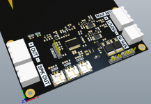
Lockdown allowed for time.
I experimented with a dedicated supervisor circuit.
I have managed to complete 70% supervisor layout and 90% of the firmware is done as well.
Here is what it can do.
- x2 dc monitor voltage +/- up to 100V (programmable 1V steps).
- x1 dc offset +/- (programmable 1V steps).
- x2 +/- current rail monitor 20A (programmable)
- x3 temperature sensors each programmable.
- x1 signal shutdown command output.
- x1 switching frequency monitor.
- x1 4-wire fan output + Fan RPM monitor.
- x1 solid state relay. (will upgrade to x2 for full bridge application)
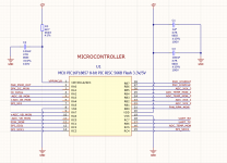
- x1 SPI control and communication. (I2C "master mode" is a dog to get right on a PIC16F18857)
The cost of doing this is no more than $20 parts, but the firmware took a while to get right. I have a breadboard of it working on the desk.
I experimented with a dedicated supervisor circuit.
I have managed to complete 70% supervisor layout and 90% of the firmware is done as well.
Here is what it can do.
- x2 dc monitor voltage +/- up to 100V (programmable 1V steps).
- x1 dc offset +/- (programmable 1V steps).
- x2 +/- current rail monitor 20A (programmable)
- x3 temperature sensors each programmable.
- x1 signal shutdown command output.
- x1 switching frequency monitor.
- x1 4-wire fan output + Fan RPM monitor.
- x1 solid state relay. (will upgrade to x2 for full bridge application)
- x1 SPI control and communication. (I2C "master mode" is a dog to get right on a PIC16F18857)
The cost of doing this is no more than $20 parts, but the firmware took a while to get right. I have a breadboard of it working on the desk.
Attachments
Last edited:
Good luck. they were rare before the pandemic, now its close to impossible.. soic versions are mostly out of stock. I assume you understand this.
Flee Bay. fakes are an issue you could get lucky.
NEW 1PCS IR IRS2092PBF IRS2092 DIP-16 PROTECTED DIGITAL AUDIO AMPLIFIER | eBay
Flee Bay. fakes are an issue you could get lucky.
NEW 1PCS IR IRS2092PBF IRS2092 DIP-16 PROTECTED DIGITAL AUDIO AMPLIFIER | eBay
- Home
- Amplifiers
- Class D
- SystemD LiteAmp