But there seems to be no single frequency which can be used for the full duty cycle range...
Even in amps which are intended to run clocked only, staying locked at extreme duty cycles is often not given. Carrier aliasing becomes headache the higher loop gain is and again more headache in post filter designs. It is pretty common that the upper 3db suffer from this, in some designs even the upper 5db...
There are countermeasures, but for the lite amp they are all to complex.
Forcing fs of the LiteAmp needs a very different paramterization than the IRAUD, because of the different loop structure, but basic clocking principle is the same.
Clocking down as proposed by IR inflates the harmonics in an pretty hefty way, because different from changing the self oscilating frequency now in forced operation the carrier shaping is not adjusted to the frequency any more.
Clocking up is by far more forgiving than clocking down with respect to THD.
But no lunch for free - clocking up offers less locking range.
Overall the first experiments showed options to achieve acceptable results, so I will include the clocking option. Later optimization is possible and might also depend on the personal taste of the user.
Hi All and especially Chocoholic (Martin?),
I'm jumping on this train and hoping to learn some things along the way.
I have a hard time grasping all the details of the PWM modulation and control loop stability, but on the other hand, I'm experienced in power electronics, so FET driving and board layouts that discourage ringing have little secrets for me. I'm already half-way then, I guess.
I'm first going to start some simulations in LTspice, based on the other threads mentioned here.
Cheers, Marc
I'm jumping on this train and hoping to learn some things along the way.
I have a hard time grasping all the details of the PWM modulation and control loop stability, but on the other hand, I'm experienced in power electronics, so FET driving and board layouts that discourage ringing have little secrets for me. I'm already half-way then, I guess
.I'm first going to start some simulations in LTspice, based on the other threads mentioned here.
Cheers, Marc
... experienced in power electronics, so FET driving and board layouts that discourage ringing have little secrets for me. I'm already half-way then, I guess
Hi Marc,
yes, especially the ringing makes many DIYers fail... ...suffering from 'unexplainable' defects, or early action of protections, or simply poor overall performance and running unnoticed EMI vulcanos...
So your starting point seems to be fortunate.
Take care, classD can easily happen to become a passion !
! Markus
Member
Joined 2009
Paid Member
Oohps, not everybody is of your opninion.I like this thread
Two votes. The first vote was 5 stars, now there are two votes and the average dropped to 3 stars.
Looking like a clear dislike of somebody.

Don't care! There is always one out there which goes green with envy - hence the bad vote.Oohps, not everybody is of your opninion.
Two votes. The first vote was 5 stars, now there are two votes and the average dropped to 3 stars.
Looking like a clear dislike of somebody.
BR, Toni
Thanks a lot
..now the response was by far stronger than I had expected...
Many thanks for all the good ratings
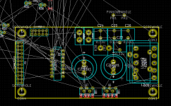
In the moment there is nothing special to show.
Started with the PCB and have to notice that my intesion to
bring the main board with a 100mm x 50mm size will become
pretty compressed, because of the many options + daughter board +
being prepared for the higher power version + using mostly wired components. Most likely I will have to use lots of vertically placed resistors.
Ugly, but the PCB will clearly show at which side has to be the body and which side has to be the wire ...
Hope vertical resistors are not a hard NoGo for you - or if it is a hard NoGo, please veto now and let's find a trade off.
The trade off moves between larger PCB, or more SMD, or allowing to place axial components in vertical manner, or canceling alternative component options like for the choke.
..now the response was by far stronger than I had expected...
Many thanks for all the good ratings
In the moment there is nothing special to show.
Started with the PCB and have to notice that my intesion to
bring the main board with a 100mm x 50mm size will become
pretty compressed, because of the many options + daughter board +
being prepared for the higher power version + using mostly wired components. Most likely I will have to use lots of vertically placed resistors.
Ugly, but the PCB will clearly show at which side has to be the body and which side has to be the wire ...
Hope vertical resistors are not a hard NoGo for you - or if it is a hard NoGo, please veto now and let's find a trade off.
The trade off moves between larger PCB, or more SMD, or allowing to place axial components in vertical manner, or canceling alternative component options like for the choke.
Attachments
..now the response was by far stronger than I had expected...
Many thanks for all the good ratings
In the moment there is nothing special to show.
Started with the PCB and have to notice that my intesion to
bring the main board with a 100mm x 50mm size will become
pretty compressed, because of the many options + daughter board +
being prepared for the higher power version + using mostly wired components. Most likely I will have to use lots of vertically placed resistors.
Ugly, but the PCB will clearly show at which side has to be the body and which side has to be the wire ...
Hope vertical resistors are not a hard NoGo for you - or if it is a hard NoGo, please veto now and let's find a trade off.
The trade off moves between larger PCB, or more SMD, or allowing to place axial components in vertical manner, or canceling alternative component options like for the choke.
Did some googling and found this and a lot more :
"Mounting a resistor vertically creates a bigger loop that can pick-up interference magnetically. Compare this with a resistor being mounted on the PCB flat against a flooded ground-plane. The voltage pick-up level is proportional to frequency and area of loop formed by the resistor. This is why surface-mount resistors are preferred a lot of the time.
Also, A high value resistor mounted vertically is also asking for trouble in the presence of HF electric fields - what you can create is a mini-antenna.
As for pull-ups and downs, surely you won't be swapping these out in your prototype - I'd consider using surface mount devices for these parts."
Have no idea if this is a valid statement .
Would not have any problem with SMD parts , 3 days no coffee and beer and solder on !
Most PCB suppliers offer SMD parts placement for little cost . See LJM's LxxD's and Christi's kit , they come with pre soldered smd parts .
As for the Choke , just go for the best one ! it's post filter so one value suits all speakers .
Cheers ,
Rens
Last edited:
It is definitely a valid statement.... no idea if this is a valid statement .
That's why it is important where to put the body and where the wire.
Loop size won't change, but at least one can control which part has a
low or high impedance vs the GND plane...
I am confident that I can achieve a sufficiently good layout this way,
but going for SMD would be better, 4 sure.
Personally I am perfectly comfortable with soldering resistors and caps of 0805 size.
(Smaller becomes more and more pain. Pitches like the LT1711, are really the limit I can handle and definitely heavy pain.)
Question to all:
Would you agree to an increased amount of 0805 SMDs or larger?
IRS2092 would still remain DIP.
doctordata's view is in principle correct, but e.g. "MyDOA" uses only vertical mounted resistors and hasn't more problems picking up RF as a commercial opamp which is very small compared to MyDOA ...
My old eyes and fingers hate those small smd parts. Every second part will get lost during mounting. Sometimes you here a creak under your shoes ...
Needed to use small smd caps in my class D project to fulfill datasheet requirements of TDA8950J. If you solder them too long the caps simply explode after first power on ...
In other words: if only some parts need to be smd and those smd parts are big enough I'm willing to solder them ...
astx & gommer ... you are obviously living on different planets
Ok, in first step I will see if I can follow the request for easy DIY of astx.
Already changed the few SMD from 0805 to 1206...
That's going to be a nice puzzle
In fact I like to do layout work. At least when time doesn't matter.
It feels like sort of meditation. ...thoughts drifting from simple hard limitations over geometrics to 3D-fields... Don't ask why I like it.
Attachments

Hi All,
Please tell me if this is not the right place to post this. But here is my first failing attempt to roughly simulate teh IRS2092, based on the IR reference design. As you can see, it saturates without any sign of oscillation. Can any of you experienced builders see the fault? I'm assuming it might be the comparator reference (now GND).
This schematic is purely meant to learn the basics and see how it (roughly) reacts to component changes. I know it's not coming anywhere near Choco's design.
TIA for any help.
Attachments
... think some 1206 can be handled by my old hands and we save some money cause we do not need the costly premounting by pcb manufacturer ...astx & gommer ... you are obviously living on different planets
Ok, in first step I will see if I can follow the request for easy DIY of astx.
Already changed the few SMD from 0805 to 1206...
...

Eyes get older and parts become smaller - this is a real challenge for DIY. My actual "pain limit" is SMD 0402 even working under a microscope. I do my layouts since decades and "converted" to smd for some time - the layouts are definitely much better than with THT.
So I think SMD1206/0805 are a good comprose for all.
So I think SMD1206/0805 are a good comprose for all.
OK, that was a very basic mistake. Solved it myself: there was no feedback in the system. Apparently the driver stages in the IRS2092 make another inversion, which I didn't have in my simulation. This now seems to be pretty good for a first attempt, as the self oscillation in this configuration is 360kHz.
Is this anything that resembles what you guys use for simulations?
Is this anything that resembles what you guys use for simulations?
Attachments
- Home
- Amplifiers
- Class D
- SystemD LiteAmp