You mean you see in your FFT a fuzzy -100db floor?!?!
CDA-224, which is a clone of the IRAUD7 is 20-30dB better, but still to noisy.
THD of the CDA-224 was IMHO OK. May be not perfect, but OK.
Have a look here in posting #42 (comparison of different dead times).
With the original dead time setting of 45ns the CDA-224 is not so bad and
close to the IR promises.
Can you show your measurements?
FFT of noise floor is exactly as shown in IR's published measurements of IRAUDAMP7S. I have confirmed this be repeating their measurements on a sample of the actual reference design board using AP 2722. I'm curious how CDA-224 can possibly be 20-30dB better, unless the gain has significantly been reduced from the 36dB of the reference design, and even then I find it unlikely. All of IR's reference designs utilizing the IRS2092 seem to have a similar noise floor.
THD is also as shown in the reference design measurements. Not bad, but not exceptional.
The -100db noise floor in the application note is related to a 1Vrms output signal. My measurements on the CDA-224 have been with 10W/4R means 6.3Vrms.I'm curious how CDA-224 can possibly be 20-30dB better, unless the gain has significantly been reduced from the 36dB of the reference design, and even then I find it unlikely.
I will have a look the at 1Vrms, most likely results will come closer there.
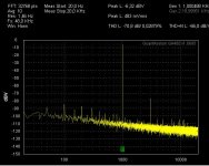
Here the measurements with 1Vrms into a 4R load.
The absolute voltages in the display of the QA400 do show the level at the input of the QA400, not the absolute value of the amp output.
Between QA400 and DUT I have a filter and adjustable buffers, running the QA400 always in its sweet spot around 700mV (500mVrms single tone).
Please also note that this sweet spot means the peak of my 1kHz is at -6db (while the AP2 scales the peak to 0db), so the floor also is shifted by 6db...
IMHO the findings with the CDA-224 fit acceptable to the application note of IR.
First picture:
CDA-224, please ignore the hum - it is a short coming of my placement in the specific enclosure.
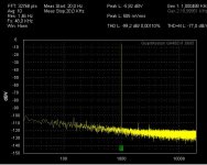
Second picture:
The LiteAmp with a voltage gain of 10.
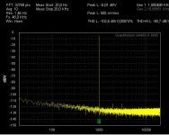
Third picture:
The LiteAmp with a voltage gain of 5.
Would you prefer to go for the low voltage gain of 5 in order to achieve the lowest possible noise?
Please note that this would require to use the optional gain stage daughter board in most applications.
For me it would be OK to go for the lowest noise.
The absolute voltages in the display of the QA400 do show the level at the input of the QA400, not the absolute value of the amp output.
Between QA400 and DUT I have a filter and adjustable buffers, running the QA400 always in its sweet spot around 700mV (500mVrms single tone).
Please also note that this sweet spot means the peak of my 1kHz is at -6db (while the AP2 scales the peak to 0db), so the floor also is shifted by 6db...
IMHO the findings with the CDA-224 fit acceptable to the application note of IR.
First picture:
CDA-224, please ignore the hum - it is a short coming of my placement in the specific enclosure.
Second picture:
The LiteAmp with a voltage gain of 10.
Third picture:
The LiteAmp with a voltage gain of 5.
Would you prefer to go for the low voltage gain of 5 in order to achieve the lowest possible noise?
Please note that this would require to use the optional gain stage daughter board in most applications.
For me it would be OK to go for the lowest noise.
Attachments
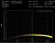
...and here the gain 5 with A weigthing...
The -84dbV (A) fit nicely to the noise which I get visualized with my noise amp and scope: 65uVrms
Related vs intended full output power (22,4Vrms) this translates to a normal advertising specification of SNR:110db
I think we should go for the low gain, because with this we achieve
noise figures which are normal for class A/B amps.
Attachments
Would need 4 bridged channels.
This is sounding like you are intending something which I would not recommend. It is not helpful to run everything in bridged mode without need.
Despite the fact that I expect for the LiteAmp similar trouble free operation like in my 2kW amp in bridged mode, I generally do expect inferior performance in bridged mode.
In bridged mode the load brings a noticeable impedance between both amp outputs, means you couple them. Switching residuals from one amp now can enter the feedback signal of the other one, and vice versa.
The amount of impact will depend very much on your particular set up / load parameters. Typically such effects turn visible in FFT by increased distortion and a more fuzzy noise floor.
Even if I expect trouble free bridged operation - for best audiophile performance I do recommend to use the unbridged for most chanels and
bridged only where you really need the power. I.e. for the sub.
P.S.
Regarding bridged mode IMHO post filter solutions are generally more picky than pre filter. And self oscilating again more picky than clocked.
True, even if I prefer the AD8620 - basically any normal OP amp will do the job.I doubt line-level gains should be an issueEven if the input impedance is low, slap a good ol' NE5532 in front of that, and call it a day
The nice thing with the intended daugther board is that it opens an uncritical area to experiment according personal taste.
...
Even if I expect trouble free bridged operation - for best audiophile performance I do recommend to use the unbridged for most chanels and
bridged only where you really need the power. I.e. for the sub.
...
Yes - bridged for sub to get > 200W8R. Mid speaker and tweeter will be driven by single amp with adapted gain.
But bridging would be obsolete for me if we get > 200W@8R with
two paralleled IRFI4019 or IRFI4020, running from about +/-70V ... ?
If we go for gain 5 we should think about output performance of used opamps delivering high output voltage swing. I have done some test some months ago with gain 20dB and output 600R with 7Vrms:
opamp_comparison_20kHz_at_7Vrms
BR, Toni
opamp_comparison_20kHz_at_7Vrms
BR, Toni
..bridging would be obsolete for me if we get > 200W@8R with
two paralleled IRFI4019 or IRFI4020, running from about +/-70V ... ?
Do I hear a customer demand for a version with higer rails
?Understood - will keep this point in mind during final design of the +/-40V and layouting.
Please note, so far I have not even done the simulation of the higher voltage version.
Just looked at some very basic points of the IRFI range.
Earlier I intended to go for even 4R operation at +/-70V, but after reviewing the data sheets (especially body diode and allowed power dissipation), it might be a better idea to allow 4R operation only up to +/-60V, but 8R up to +/-80V. ...also will have to look if I stay with 400kHz, or go for a lower fs.
Switching losses of the body diodes are no fun.
In any case your request for >200W/8R should be definitely realistic.
...will have to run simulations of the +/-50...80V version, when I want to get the layout usable for both versions.
Stepping up involves more than just looking at the Fets.
- Concept for the auxiliaries
- Reducing the fs is good for the MosFets but bad for choke size
- Cooling concept
- Snubbering
....

Stepping up involves more than just looking at the Fets.
- Concept for the auxiliaries
- Reducing the fs is good for the MosFets but bad for choke size
- Cooling concept
- Snubbering
....
Do I hear a customer demand for a version with higer rails
...
In any case your request for >200W/8R should be definitely realistic.
Very good!
...
- Concept for the auxiliaries
....
Would use external analog power supply using e.g. LM317/LM337 to get best PSRR for the opamp front end.
Hi Toni,Would use external analog power supply using e.g. LM317/LM337 to get best PSRR for the opamp front end.
personally I definitely intend to derive all the auxiliaries from the power rails. Most of my earlier amps did not offer this and despite some technical advantages I learned to dislike the resulting wiring efforts...
But I can provide an option to feed the daughter board from an external supply.
Hi Rens,Would be nice to have an adjustable switching frequency in case multiple channels are used and either match them closely or keep them apart above audible range.
welcome to the Lite Amp
Alright, I can easily add an adjustment between approx. 340kHz-440kHz.
The overall set up leads to a sweet spot somewhere around 390kHz..400kHz. (Trade off between distortion, loop gain/step response, idle losses of the output choke, carrier residuals at the output ....).
Fs can be adjusted from 340kHz to 440kHz by a pot without messing the tuning to much. Everybody who does not like the pot, can jumper it and simply put the demanded overal value in a resistor, which is in series to the pot/jumper.
I did like this part of the feedback structure from IR, so I incorporated it in the lite amp.
 to all
Markus
Protection Protection
Hi Markus ,
Any thoughts about protection ?
There are nice new developments in the SMPS field , for instance the new 2kW power supply from Connexelectronic Connexelectronic and the smaller Connexelectronic with build in DC fast disconnect ( requires a logic High to shut down the PSU if I understand correctly ) and logic mute output to prevent power on and off noises .
Would spare us DC protection relays and / or Mosfets circuits and their distortion in the signal path .
I ordered Christi's new 2 kW power supply's some time ago to play around with , so I should receive it shortly and can tell you more about it .
Cheers ,
Rens
Last edited:
...
But I can provide an option to feed the daughter board from an external supply.
...
Thats fine if you provide jumpers and e.g. a 4 pin header "+/GND/GND/-" or similar on the daughter board. Also the switching frequency tuning is cool.
Think I have read anywhere in the IRS2092 datasheets or application notes there is a too short explained example how to syncronize the switching frequency among several amplifiers. Would this help for bridging?
Any thoughts about protection ?
There are nice new developments in the SMPS field.....
....with build in DC fast disconnect ( requires a logic High to shut down the PSU if I understand correctly ) and logic mute output to prevent power on and off noises .
Would spare us DC protection relays and / or Mosfets circuits and their distortion in the signal path .
KIS, keep it simple is one of the main targets of the LiteAmp.
- Overcurrent protection comes for free with IRS2092
- Proper concept and parametrization of the auxiliaries ensure that the amp turns on without klick/bump and turns off without any screaming noise - no matter how fast or slow the +/- rail ramps up or down.
- Overtemperature protection is also not needed, because I decided to go for a L-profile as heat sink (below PCB and one side) ==> solved by thermal headroom, much more than the already sufficient heat sinks off my breadboard.
- 90% of the DC speaker killer events are caused by amps without proper over currrent protection or thermal issues. Hopefully both is good enough in the LiteAmp to keep low the likelyhood of heavy DC output.

Still there remains a certain risk - correct.
IMHO an universal solution for DC-protection would need a relay or solid state relay in series to the speaker.
The solutions without relay/solid state relay are only good for designs where the amp and PSU are coming from the same system provider, because:
Most PSU do not offer this shut down input, and the ones which do offer it are not standardized. Some need a logic high with 5V, others need an open collector pull down... All of them force the amp to use auxiliary supplies, which remain active during shut down...
Overall I came to the conclusion to skip it, in order to avoid complexity for a feature which will be used by just a few guys.
Do you think that's a bad plan?
You mean this? Page 4?..have read anywhere in the IRS2092 datasheets or application notes there is a too short explained example how to syncronize the switching frequency among several amplifiers. Would this help for bridging?
http://www.irf.com/technical-info/appnotes/an-1138.pdf
So far I did not dig into it. But basically it should be also possible in the LiteAmp. Key question is whether this forced operation will not generally degrade the performance to the level which in the other case might accidentially happen by uncontrolled partial sync. Generally it will not avoid the HF coupling from carrier residuals to the others chanel feedback. On the other hand, when properly synchronized this effect might be less harmful. I will have a look to it.
KIS, keep it simple is one of the main targets of the LiteAmp.
...
Do you think that's a bad plan?
...
Full agree and very good plan! The IRS2092 itself has many protection features and shutdown/dc protection can be done by external components to keep the pcb simple.
E.g.: I have designed my own microcontroller circuit to control ac power, dc for 4 speaker outputs, mute, remote power on/off, 3 temperature zones.
Exactly! But there seems to be no single frequency which can be used for the full duty cycle range...
BTW: I have some different 1200W SMPS PSU's on stock for testing ...
(2x46Vdc; 2x64Vdc; 2x85Vdc)
BR, Toni
- Home
- Amplifiers
- Class D
- SystemD LiteAmp