Do I need to put a bulb on both sides?? I would think so... I can make that happen .. This would save the fets I suppose..
I feel like I have checked pretty much everything.. LOL.. but I must be missing something.. Hard to check some of the stuff as it feeds back thru other things and I get weird reading.. I was wondering about the resistors and such in the output filter section.. if those were bad would that take out fets? I suppose it could. I wouldn't think that anything in the preamp section would .. that could effect the input audio.. but the power amp section should still work..
If there was something screwy with the feed back loop .. would that cause problem? I am still a little fuzzy on the self oscillation thing and what is needed to make that happen... Lets way for instance if the feed back was removed.. would the outputs of the 20957 still generate a square wave? I am considering removing the IC H04 which is the final IC before the inputs to the IC so remove that from the equation. but want sure if the feed back was needed..
Do you know about the VS voltage ?? I find it somewhat strange that it runs at +10V... So my -B to VS is like 85 V and +B to VS is 65 V..
This is with or without a load.. I could see a volt maybe but I don't get why its so high.. maybe it doesn't matter.
Thanks again.. sorry to be a pain.. just trying to figure this thing out.. I hate not being able to fix stuff.. LOL..
Do I need to put a bulb on both sides?? I would think so... I can make that happen .. This would save the fets I suppose..
If there was something screwy with the feed back loop .. would that cause problem? I am still a little fuzzy on the self oscillation thing and what is needed to make that happen... Lets way for instance if the feed back was removed.. would the outputs of the 20957 still generate a square wave? I am considering removing the IC H04 which is the final IC before the inputs to the IC so remove that from the equation. but want sure if the feed back was needed..
Yes, you will require two bulbs to current limit both asymmetrical +/- rails from a short circuit.
Its not hard to determine the type of modulator, self oscillation will not produce "oscillation" if the feedback loop is broken, even a small cap/resistor will obfuscate the problem (this is the hardest style of amplifier to debug) you don't seem to have a self oscillation problem, you have a low resistance path that's causing 20957 IC to malfunction.
Not sure if the diagram you supplied is 1:1 a copy maybe close (don't assume though) if its the case try removing L (coil) from the LC filter, there is a configuration that's manipulating the input signal gain via a blown/shorted transistor configuration that maybe be influencing VS of the 20957. (as its connected directly to output stage of the mosfets)
Last edited:
No its not 1 : 1 Some of the resistance values are different and such.. BUT as far as the layout supporting the 20957 its identical ( The one thing that sticks out to me is the supply of VDD from the +15V vs the +B ) and input path for the signal and feed back path it is identical. One question I had was what is the purpose of D55 and D57 on the input .. just wondered.. The only thing I can see that is not the same is the The Power OFF check circuit, and the Amp Mute Low Level Mute circuits after the L coil.. They are not part of my pcb.. and thus should have no effect. the rest are there even the input limit circuit that feeds back to the Optical resistor.. Anyway.. Back to the modulation thing.. So if I understand.. we have to have some sort of square wave coming in at pin 3 for the outputs to keep oscillating right ?? outputs follow input right?? So if we just grounded pin 3... nothing would happen at the out puts ?? (LO and HO) or just LO would turn on.. or what would happen if we just put in 5v Just HO ?? .. I guess. what im getting at is I wonder if I have some issue with the input to pin 3 causing the IC to just turn on the FET and thus they short out..( feed back loop broken so it wont oscillate) also trying to understand what to expect from the outputs side of the IC.. HO and LO..and what to look for.
Again.. thanks for your time and help.. I have like 90% understanding.. of all this.. lol.
I'm just unclear about how the IC starts to oscillate the output...and if it needs input to do this.. or it just does it on its own..
Thanks.agian.
Again.. thanks for your time and help.. I have like 90% understanding.. of all this.. lol.
I'm just unclear about how the IC starts to oscillate the output...and if it needs input to do this.. or it just does it on its own..
Thanks.agian.
No its not 1 : 1 Some of the resistance values are different and such.. BUT as far as the layout supporting the 20957 its identical ( The one thing that sticks out to me is the supply of VDD from the +15V vs the +B ) and input path for the signal and feed back path it is identical. One question I had was what is the purpose of D55 and D57 on the input .. just wondered.. The only thing I can see that is not the same is the The Power OFF check circuit, and the Amp Mute Low Level Mute circuits after the L coil.. They are not part of my pcb.. and thus should have no effect. the rest are there even the input limit circuit that feeds back to the Optical resistor.. Anyway.. Back to the modulation thing.. So if I understand.. we have to have some sort of square wave coming in at pin 3 for the outputs to keep oscillating right ?? outputs follow input right?? So if we just grounded pin 3... nothing would happen at the out puts ?? (LO and HO) or just LO would turn on.. or what would happen if we just put in 5v Just HO ?? .. I guess. what im getting at is I wonder if I have some issue with the input to pin 3 causing the IC to just turn on the FET and thus they short out..( feed back loop broken so it wont oscillate) also trying to understand what to expect from the outputs side of the IC.. HO and LO..and what to look for.
Again.. thanks for your time and help.. I have like 90% understanding.. of all this.. lol.
I'm just unclear about how the IC starts to oscillate the output...and if it needs input to do this.. or it just does it on its own..
Thanks.agian.
I thought you trying to debug the issue with the 20957 IC destroying itself without the output stage ?
If the IC is not driving any mosfets it should NOT destroy itself (even if both outputs are driven. with or without PIN-3 off/on, besides the IC uses bootstrap so high side drive is determined by the low side mosfets drive.
if the low side (outstage) dont work or is not present as in this case, high wont work, have you checked the low side output ? PIN 10 (L-drive) there should be signal on that pin, but not on H-PIN
How many 20957/mosfets have you destroyed so far??

to understand how class d modulators works read this
....::: HIFIAkademie.de :::....
LOL. to many, Well lets see.. I think I ordered 10 Fets.. I have 2 left.. lol.. I am trying to debug/fix the whole thing. Just to refresh the symptoms that led to this.
1) The amp seemed to have half power it was going into protect but not nearly the power ouput it should have.
2) then finally it stopped working completely.. Power LED would not even turn on.
3) I pulled it apart. found FETS shorted on one side. ( thus no power as SMPSU was protecting itself) Also I determined the 20957 was toast.
4) replaced the FETS and the 20957.
5) power up unit. ( no load) Power light comes on.. and I can see Protect light come on that off.. then on. .then off.. I can see Voltage at Pin 2 cycle between 2.5 and 7.5 as expected. At that time I was looking at VS and seemed like I could see it going positive to +B.. on one side , and only about half of +B on the other.. so possibly thingking back that side may be the problem.. anyway..
6) did some poking around and testing and voltage checking and at some point took out the FETS on the other side.
7) replaced all 4 FETS and both 20957's Power up.. No OC cycle.. but no oscillation.. either.. Poking around found that the H04 IC ( last before inputs to 20957) seemed bad. Weird voltages and resistances.. more checking.. and at some point the FETS shorted again.
8) Replaced the H04 IC now with a Sine wave in.. I get a square wave out of the H04..To Both 20957's ( My thinking was that possibly this ic went bad in the first place and started all this as it has to feed the square wave into both 20957's One obviously the invert of the other.) Replaced the 20957s and Fets again.. No clip led.. but I still see the OC cycle going on.. This time when I look at VS i don't really see it switching and can maybe see some pulse at LO on the one side ( my scope just triggers for a brief moment in sync with the OC cycle) nothing on the HO .. on the other side.. i don't seem to see anything at LO or HO.. more poking around. FETS burn out again.. That's were im at... LOL...
seems like The 20957s are fine if I don't have any Fets in.. They will sit there and the OC protect cycle. I assume that with out FETS the OC will cycle because VS is just sitting at 9V and it should be going to -B or + B.. so to the IC that would look like Vds is +B or -B.. So I think I have to have FETS in.. I think I have multiple issues.. idk.. I don't think this should be so damn hard to figure out.. LOL..
anyway.. I think when I poke around with power on .. it is maybe causing the FETS to go.. idk.. they don't go right away.. it just OC cycles. I'm just missing something basic I think.. over thinking it...
Thanks again for the input and ideas.. helps to think thru stuff and get back on track.
Just to add .. my concern about the feed back.. if you look at the schematic.. the feed back comes in previous to the H04 ic..( H04 IC is U21A U21B U21C on the schematic) So if that IC took a crap.. the feed back would not be getting to the 20957's.. and there would be no Pulse type input.. Before I realized it was toast, the in put to the 20957's was 3.5 Vdc on one side and 4.8 on the other..
So if you just put straight DC into them.. what happens.. ? probably not good.
So if you just put straight DC into them.. what happens.. ? probably not good.
Poking around with it switched on will blow things up.
I blew numerous irs2092's before I figured that one out.
The 20957 will go into protect with no mosfets in. The IC will look for a over voltage across the lower mosfet and will find one.
What I did see once that threw me was a none shorted mosfet DS that was shorted GS.
I also learned not to replace mosfets without replacing irs2092 or more often than not everything would fry again.
One more thing.. the High side will have Boot strap even if the Lo side doesn't work because there is a precharge resistor .. R 14 and R 15.. What I don't get is why do you even need the Boot strap Diode and resistor if you have R14 and R15 to charge it before the LO side turns on.. idk..
One more thing.. the High side will have Boot strap even if the Lo side doesn't work because there is a precharge resistor .. R 14 and R 15.. What I don't get is why do you even need the Boot strap Diode and resistor if you have R14 and R15 to charge it before the LO side turns on.. idk..
I am very familiar with a IR2010 I can simulate bootstrapping by supplying -VCC charging up the cap and get both output L-OUT AND H-OUT to signal (with load resistors on both to simulate RC gate charge) this works fine for me. You can probably do this for the 20957 as well (trick it as well) you just need to read the datasheet until you understand it , the app notes I linked would have given you this trick for free, you didn't read it enough times, I spend a full day reading those datasheets and a week doing mock demos.
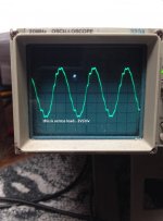
Hi Guys.. Well. some update... I added the Light bulbs for current limit. Haven't seen them flicker yet..LOL.. I replaced the FETS again and the 20957 ic's I also basically went thru the whole layout of the amp vs this schematic I found and it is basically identical except for a few variations in resistor values and such.. and mine doesn't have some of the additional circuits on the output. It only has the limit circuit that feeds back to the Optical Resistor.. Anyway. After firing it up.. IT still goes into OC cycle.. Boo. But I can see some wave forms now and I can see One side looks like square wave at VS and other looks like crap. I pulled the 20957 ic off from the side that looks like crap.. and found that the other side now stays on and oscillates.. So.. One side seems ok.. the other is not. Since I was able to now keep it on .. I took some pics of some of the wave forms I'm getting.. My LO seem to look like I would expect.. But my HO is not what I was expecting.. yet. I seem to get a good square wave at the VS.. anyway.. I will post.. If someone that has more experience with this can take a look and tell me if what Im getting is expected I would appreciate it.. I will try to label them so it is clear what were looking at.. Thank again for your help.. I think I'm close.. just missing something..
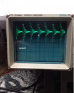
Here are some wave forms.. While the amp was OC cycling, I could see these waves for a moment before it cycled. I noted the Bad side had a strange looking wave. When I removed the 20957 on the bad side. Then the good side was stable and I could capture these.. I noticed the Bad side still as the same weird looking wave. I assume the good side is feeding back thru something causeing this?? But if so.. then I wonder why same wave was there when it was OC cycling.. anyway.. Not sure 100% what I should be seeing at H0 to VS or Vgs.. seem like I should get square wave but you can see what I was getting. Thanks.. again.
Sorry here are the waves I also included the Schematic again for reference.. Page 2 is the amp section
Attachments
-
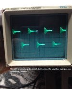
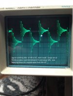 HO to VS.jpg408.7 KB · Views: 773
 -
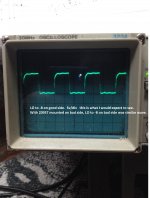 LO to -B.jpg306.6 KB · Views: 705
 -
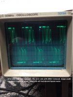 VS to ground load removed bad side.jpg333.8 KB · Views: 681
 -
 Vbs.jpg301.2 KB · Views: 672
 -
 Vload.jpg332.2 KB · Views: 645
 -
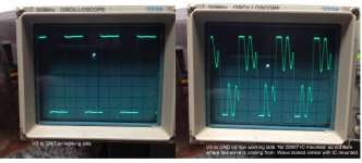 VS to ground both sides.jpg485.8 KB · Views: 176
 -
 vs to not sure.jpg164.3 KB · Views: 164
 -
SVT 7_ Main Bd.pdf870.3 KB · Views: 423
- Status
- This old topic is closed. If you want to reopen this topic, contact a moderator using the "Report Post" button.
- Home
- Amplifiers
- Class D
- Behringer 1400W Class D for B1800D Repair help!!