continued: the 7912? The amp has a +/-12 supply for the op amps and other chips on and off the main board.
If I omitted any warnings I apologize,This is a learning process for me as well as you. This is a set back but in the end you will fix this amp and we will both learn a thing or two about fixing amps and teaching/training tech's through a forum! Part of my job is training,so not my first rodeo but a different arena! :0)
If I omitted any warnings I apologize,This is a learning process for me as well as you. This is a set back but in the end you will fix this amp and we will both learn a thing or two about fixing amps and teaching/training tech's through a forum! Part of my job is training,so not my first rodeo but a different arena! :0)
Sorry about the discontinuity (no pun intended) I was edited and ran over the administrator time limit.
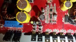
So, it sounds like whatever shorted will be on the main board, that will narrow down where the fault is.
You will see a half dozen parts around the 7812. a couple of capacitors and resistors. Can you take a close up of the 7812 and surrounding parts so that I can inspect the parts? I will study the pics you have sent and let you know what resistors and capacitors you should check with the ohmmeter( Power off of course :0) after you send me a pic, can you remove the shorted 7812?
Man thanks a lot for having the patients to work with me. I know that can be agitating at times.
But I'm as work still got another 6 hours before I'm off, when I get back I will take a pic for you this time ill try to use my other camera if I can find it, its like 10mpix so it would be a lot better than the ones from my phone
It sounds like you got a fun job ... teaching electronics for loud music
I did computers similar at finding problems in a way but swap whole board or part instead of chips and buses lol
It wilm be late when I'm off so if I don't hear from you later ill talk to you tomorrow off work so will have plenty of free time
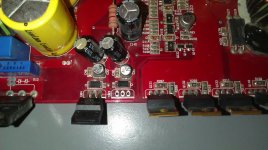
Okay, here is a close up picture. It's the KIA7812A on the right side of the two KIA's. And yes, if you would like me to remove the mosfet, I can.
But again--new at this, so what is the correct and safest way to remove/solder? What gauge of soldering wire will be needed to solder it back together? And what kind would you recommend? I know there's wire with and without lead. Didn't know if that would matter too much.
But again--new at this, so what is the correct and safest way to remove/solder? What gauge of soldering wire will be needed to solder it back together? And what kind would you recommend? I know there's wire with and without lead. Didn't know if that would matter too much.
Attachments
Obviously do not solder with power on and disconnect from your power supply. :0)
Short the power and ground terminals, I use a pair of needle nose pliers, or you could use a length of wire,speaker cable or lamp cord will do. You can use 60/40 .6mm or medium gauge solder purchased from Radio Shack or a home improvement store such as Lowes or Home Depot. Do you have a solder iron? And you may want to purchase a desolder tool, its a plunger that sucks up the solder and maybe some solder wick/braid. when you replace any parts you'll need to clean up the solder left in and on the pads/via's so that you can install new part/s.
After you remove the 7812 check the resistances from power ground terminal to all three of the holes where the 7812 was. Tell me what you find. I'll will consult my schematics tomorrow. I think the 7812 and maybe the LM361 will need to be replaced, all though there may be one or two more parts to replace. If you have a Radio Shack you might find the 7812 there and any tools or solder you'll need.
In the meantime, you can continue tracing the trace for the relay. you might start from the relay side and study the pins of the relay from the underside of board. There are two pins for the relay coil. When you measure this with an ohmmeter you will recognize the same reading you found across the diode (160 ohms). The other two pins are the contacts and should read Hi ohms or infinity. Here's is an experiment you can try, use your 12 volt supply and place 12 volts across the coil or the diode (both are electrically the same point, which you will have proven to yourself after the previous test) Positive to the unstriped side of diode, and neg to the striped side.You should hear the relay click on, don't linger too long, remove 12 volts and you should hear it click off. If you can have someone hold the ohmmeter to the contact pins and watch the meter, you should see the reading drop to near zero. This will prove the relay works and help you visualize the internal workings of the relay. I'll will be back on later. Have fun!!
Lol I know I know, just thought I needed power going through the trace to test if they are getting anything, that was my mistake. Learning experience here
So use a small set of needle noses to helpl remove the transistor, what about the speaker wire or lamp cord?
I do have a soldering iron I will look at radio shack to see what they have and possible the KIA7812, but last time I was there about parts for this amp they had no idea what I was talking about or what would work. They showed me there drawer of transistors but the kid was just like he doesn't know much about these. not real help
So after I get the bottom pins loose to I need to heat up whats left of the pins to pull them out then clean up with desolder tool?
and after all this with spare time left and checking traces what did I miss that is the correct way to check these lol
and if radio shack doesn't have the parts I need I think I will just go ahead and order online.
If I order the KIA7812A should I replace the other KIA as well.
And most of these that I order are from china so if you want me to I can go ahead and order the KIA, The LM361N, and I been searching for the Relay online but having issues with that
The needle nose pliers I use to short the power terminals, or you can use a speaker cable or lamp cord to jumper power and ground terminals.
To remove the 7812 you can use the desolder tool, when you heat a joint with your iron and melt the solder, the desolder tool will suck up the solder. The desolder tool is a plunger and after you push in the plunger it will lock, and when your ready pushing the button on the side will release the plunger creating a vacuum and suck up the solder. The tip of the desolder tool should be as close as possibly without touching the hot solder, after you've done it a few times it will become easier. If you have a PCB lying around that can be used as a practice board that would be a good exercise. The solder braid or wick isn't necessary, it just adds a finer touch to the clean up.
To remove the 7812 you can use the desolder tool, when you heat a joint with your iron and melt the solder, the desolder tool will suck up the solder. The desolder tool is a plunger and after you push in the plunger it will lock, and when your ready pushing the button on the side will release the plunger creating a vacuum and suck up the solder. The tip of the desolder tool should be as close as possibly without touching the hot solder, after you've done it a few times it will become easier. If you have a PCB lying around that can be used as a practice board that would be a good exercise. The solder braid or wick isn't necessary, it just adds a finer touch to the clean up.
Yeah the 7812A Is easy to find but still cant find this NT90 40A relay
I can find some that are 24V DC
But none like this one
I did Order the KIA and it will be here sometime within the next week
Radio Shack wont be open until tomorrow to ask them about the desolder tool and solder wire. Lowes in my town didn't have any wire smaller than 1.5mm
And What is the Correct Way to Check Traces to make sure I am Doing them right? I thought I asked this before and skimmed over but didn't see.
checking traces can be done with an ohmmeter or continuity tester. The continuity tester which should be built into your multimeter will sound a tone when the resistances is low close to zero. So you can test without having the meter display in front of you.Visually inspect and determine the end of trace you are checking and put probes on either end. if the trace is connected and no breaks you will here a tone. Again traces run on top and bottom of board connected by vias. so you will have to find the trace on one side and where it terminates at a via, making sure the the via connects to the other side of board. and so on! Do not power up board! B-)
All traces on bottom of the board are good, the top is a little harder to see where traces are and go but most of I can tell from look at bottom and on top I don't see really anywhere that the trace could be bad.
I still only hear relay on off kick and as I said it isn't directly from the relay. I really think this could be a problem but still can not find this exact relay online anywhere.
I still only hear relay on off kick and as I said it isn't directly from the relay. I really think this could be a problem but still can not find this exact relay online anywhere.
check continuity from power term to the striped side of D92, I had it backward. you should hear tone, are an ohmmeter will read near zero resistances. If not the tracr is disconnected. Also check from the daughter board in the power supply. it is standing up near power terms. pin 5 to the unstriped side of D92. your board will have 5 or 6 pins try all of them. If no tone this trace is disconnected. If you get a tone to both sides of D92 you may want to remove relay. you might find moisture damage that has corroded contacts.Once you find the disconnection I will show you a way to repair. have you checked the 7812 connection w/o the 7812 in place?
Okay I will Check these next time I have the free time, and no the 7812 is still in the board I just got the vacuum desolder tool today. Also, how is this relay removed? does it just pull out of the board or is it solder down to the board?
Thanks and will get back with you asap
Thanks and will get back with you asap
Continuity Test From Power Terminals to either side of D92 had nothing
The Daughter Board (little one standing up with 5 pins) only one of the pins signals a tone from d92 and resistance of 158 on the other side
And from looking at the bottom to top a lot im guessing the relay has three spots it solders to the board? and think I will be getting the soldering done today to get the KIA7812 off and relay as soon as im sure what pins and how many.
Oh and if I buy a used Kicker 750.1 amp does it have to be the model like mine that top plate pulls off or will another one that looks like mine but has the screw down top plate have the same guts?
And can you post a link possible for the NT90 Relay or will Kicker sell it to me?
Sorry haven't been here with many updates or anything been a little busy these past couple of days
Okay I have the 7812A out but now need to get a new probe for my multi.
While at work the nephew had fun with some of my tools and pulled the probe end off the wire this is why I don't have/want kids lol
But I have pictures of it and the new 7812 came in the mail today
While at work the nephew had fun with some of my tools and pulled the probe end off the wire
this is why I don't have/want kids lolBut I have pictures of it and the new 7812 came in the mail today
Attachments
Okay got new test leads for multi and a new solder iron selectable 20-40 watt ... my very old 30 watt one seems to take forever to heat the solder taking 7812 out
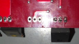
I did the resistance test that you ask for Multi was set at 200M Ohm + and - terminals jumped black lead on terminals and red testing
Pins
1: 1.1
2: 0.9
3: 0.9
If these seem right to you I will go ahead and solder my new 7812A
This Wednesday I plan on trying to take a week off to have all the time I need to finish this and so we can try to set of a time to make contact with each other as well and I'm sure we'll get a lot accomplished a lot faster that way.
- Status
- This old topic is closed. If you want to reopen this topic, contact a moderator using the "Report Post" button.
- Home
- Amplifiers
- Class D
- Kicker ZX750.1 Green Light No Output