Virpz, yeah I guess that's kinda what I was looking for....hahahaha...incredibly helpful indeed, I searched thru the thread with keyword "mono" but missed your post.
THANKS!!!!!!!
Can't blame you, the thread is already polluted with too much uselless info, kinda hard to find things .
For the output filter you should have 1 or 1.2uF instead of 0.68uF and you may also consider changing bootstrap caps. A good idea is to have some time with the TPA3116 datasheet here .
[]'s
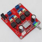
Pardon my ignorance, why are there two sets of RCA sockets? You only need one set (left and right inputs) for a stereo amp. The middle contacts from the pot should be connected to the amp inputs (left and right channels).
Regards,
Yeah I realized that later on ...sorry posting useless info

i try to implement the red yj 2.0 board better into its environment.
1.
i´m designing a preamp with an active crossover.
now i want to get the volume control away from the tpa3116 board and onto the preamp.
it should be realized with either an inverting or a non-inverting amplifier (depends on how the rest of the preamp will finally look).
what must i look for considering the given gain and impedance on the red yj board?
from the datasheet i know that the 20k and 100k input resistor make for a 26db gain and 30k input impedance.
what would a good and simple volume control based on a tl072 opamp?
please excuse my incompetence, this is the first time i'm doing something like this.
2.
i'm driving two big fr-horns with the tpa3116 board in stereo mode.
the drivers are 8 ohmers
BG 20 - 8 Ohm.
as far as i understand the board uses bd-modulation.
from another ti-doc
http://www.ti.com/lit/an/sloa119a/sloa119a.pdf
(page 11, table 2)
i understand, that the given 22uH inductor and 680nF capacitor fit 8ohm speakers.
but i do not understand the rest of the output filter.
are there serious improvements to make by changing those filters?
Last edited:
as far as i understand the board uses bd-modulation.
from another ti-doc
http://www.ti.com/lit/an/sloa119a/sloa119a.pdf
(page 11, table 2)
i understand, that the given 22uH inductor and 680nF capacitor fit 8ohm speakers.
Well, that would be the case if the switching frequency was 250khz as used in the examples in that TI-doc. However, the TPA3116 has a 400khz switching frequency so the corner frequency has to be moved up 1.6 times to have the same peaking at switching frequency otherwise you can have significant losses in the output filter coils (they get hot). Thankfully that also makes the coils much smaller and at the same time moves the filter decay out of the audible range as a corner frequency of just 28khz is quite audible as phase and amplitude of the filter affects the audible frequency range. Moving it to a 45khz corner frequency moves most audible effects out of the audible frequency range.
Please follow the TPA3116 data sheet recommendations instead of an outdated TI-doc. Or at least apply the appropriate changes.
Last edited:
I've been enjoying my red YJ 2.0 amp, but I now have a problem with the board. The volume pot no longer will attenuate the output completely. The left side will not adjust to silence. Anyone have an idea what might cause that? It is very weird. Was working normally just yesterday... I will have to investigate all the connections...
I will have to investigate all the connections...
Last edited:
I've been enjoying my red YJ 2.0 amp, but I now have a problem with the board. The volume pot no longer will attenuate the output completely. The left side will not adjust to silence. Anyone have an idea what might cause that? It is very weird. Was working normally just yesterday...
May be the volume pot is not working properly? Disconnect the power to the amp. Turn the board upside down. Measure the resistance of the pot while turning the shaft slowly to see whether there is anything abnormal. Both channels should measure about the same. Hope it helps.
Regards,
I've been enjoying my red YJ 2.0 amp, but I now have a problem with the board. The volume pot no longer will attenuate the output completely. The left side will not adjust to silence. Anyone have an idea what might cause that? It is very weird. Was working normally just yesterday...
On my second red YJ board yesterday I was thinking to a potentiometer failure (a channel was disappearing only at precise position of the pot.) but it was only a bad/cold solder of the same pot.
Just a touch with the iron, and the problem is gone.
Thanks, Lo_Tse and fritznet. Cold solder joint(s) is most likely the problem. I wiggled the pot shaft  around and was able to make the "bleed through" stop. I'll give the pot connections a shot with the iron and see if that fixes things.
Alternatively, could the metal housing of the pot at the front cause problems if it is touching the inside of the aluminum chassis?
around and was able to make the "bleed through" stop. I'll give the pot connections a shot with the iron and see if that fixes things.Alternatively, could the metal housing of the pot at the front cause problems if it is touching the inside of the aluminum chassis?
Attachments
could someone please list the best values for output filters.
for the red 2.0 board with 4ohm and with 8ohm speakers.
and for a pbtled red 2.0 board with an 2ohm, 4ohm and 8ohm speaker.
i know this thread is already polluted, i´m a worthlees noob and the datasheet gives plenty of info.
...but i don´t get it...
for the red 2.0 board with 4ohm and with 8ohm speakers.
and for a pbtled red 2.0 board with an 2ohm, 4ohm and 8ohm speaker.
i know this thread is already polluted, i´m a worthlees noob and the datasheet gives plenty of info.
...but i don´t get it...
"Best filter" I couldn't tell. But values for simple filters like TI uses in datasheet gives the 2.0 redboard a cutoff freq 29.000hz when your speakers act like 8ohm load. Matching condensators with the 22uH inductors are 0.68uF.
If you would want a 40.000hz cutoff freq with 8 ohm, inductors would need to be changed into 16uH and condensators into 0.5uF.
Using 11uH inductors with a 8 ohmísh speaker makes cutoff 58.000hz and matching condensators 0.33uF
If you chose to keep 29.000hz cutoff into 4 ohm, the inductors would be 11uH, c's 1.4uF.
40.000hz into 4ohm gives 8uH inductors with 1uF c's
58.000hz cutoff here gives 5.5uH inductors with 0.68uF
PBTL is same but for 2 ohm 29.000hz is with 5.5uH and 2.7uF
40.000hz for 2 ohm 4uH and 2uF
58.000hz for 2 ohm 2.75uH and 1.4uF
Maybe 58.000hz is too high??
Will filters with different parts but equal cutoff freq into a different speaker/load act(sound) the same?? Dont think so (Q??)... Will filters where the condensators do not give same cutoff freq as the used inductors really badly influence temperature (inductor/voicecoil) or sound??? I dont know.
Last edited:
I've suggested a wiki around page 50 or so.
Nobody was interested.
I think the same formula but for BTL each inductor is half of total inductance and each condensator double the value because in series, compared to your calculations I think???thanks irribeo.
how is that calculated?
the formula i know for rlc-lowpass-filters do not match those values.
Thanks, Lo_Tse and fritznet. Cold solder joint(s) is most likely the problem. I wiggled the pot shaft
Alternatively, could the metal housing of the pot at the front cause problems if it is touching the inside of the aluminum chassis?
No, I don't think so, most of the pot has metallic shaft and threaded that must be fixed with case, so it's a common use.
I've suggested a wiki around page 50 or so.
Nobody was interested.
Pfft. That was so 157 pages ago...
Once a Furman "power conditioner" (piece of crap, given to me by a customer I built a real conditioner for).
1 YJ Red board minus pot
1 1/4 stereo jack and 1/4 to 1/8th adapter
1 rando 15kuf cap
1 IBM Thinkpad shielded SMPS 4.5a
3 IEC cords
= 1 donated amplifier (and some speakers) to local Clay Studio.
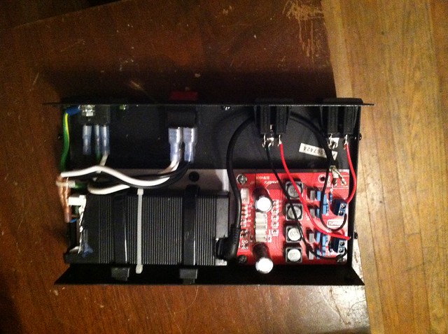
*Jack and 15kuf capacitor not seen. I left the caps stock so the lid would fit, ha. It still rocks the entire clay studio with some 4 driver (TM - MT) surround speakers by Signa.
*Jack went between the IEC inlet and lighted power switch, fit perfectly in old "reset" hole.
*15kuf cap got a thurough electrical tape wrap and was tucked between switch and one channel out.
*28ga something expensive, found in my soldering tools and parts was used for signal, twisted up and tucked down under everything else, not making contact with any power wires etc (solid core, stays in place).
*there's a little of my blood on the bottom where I drilled a hole and thought I got wipe off the "metal flakes" that were firmly attached , no sweat or tears though!
*I'm also now everyone's best friend at the Clay Studio and I'm not a member haha
1 YJ Red board minus pot
1 1/4 stereo jack and 1/4 to 1/8th adapter
1 rando 15kuf cap
1 IBM Thinkpad shielded SMPS 4.5a
3 IEC cords
= 1 donated amplifier (and some speakers) to local Clay Studio.
*Jack and 15kuf capacitor not seen. I left the caps stock so the lid would fit, ha. It still rocks the entire clay studio with some 4 driver (TM - MT) surround speakers by Signa.
*Jack went between the IEC inlet and lighted power switch, fit perfectly in old "reset" hole.
*15kuf cap got a thurough electrical tape wrap and was tucked between switch and one channel out.
*28ga something expensive, found in my soldering tools and parts was used for signal, twisted up and tucked down under everything else, not making contact with any power wires etc (solid core, stays in place).
*there's a little of my blood on the bottom where I drilled a hole and thought I got wipe off the "metal flakes" that were firmly attached
, no sweat or tears though!*I'm also now everyone's best friend at the Clay Studio and I'm not a member haha
Pfft. That was so 157 pages ago...
Yes. Now there are 157 pages more to read one by one searching for useful information.
- Home
- Amplifiers
- Class D
- TPA3116D2 Amp