So i just put together a sure electronics TPA3122 amplifier the other day. I have found that if you power up the amp to fast it goes into some sort of protection where it just clicks. If you build this amp and are having the same problem, try turning it off and on again or finding a way to apply power to it a bit slower (seems to be more of a problem when you use a higher V to power the board).
Other then that the amp is working fine but I'm not sure what I should be using as a power supply and what voltage I should run it at for the best sound.
When I power the amp up and I connect my oscope to the power and ground I can see that my power rails are directly being affected by the audio source. I also see what looks like switching noise when no audio is playing. Is this normal?
So far I have tried a 12V smps wallwart, a 29V regulated linear supply and a meanwell 24V smps (lots of clicking problems). I am seeing this on all the supplies. Should I be concerned on how modulation of the power supply lines will affect the sound of the amp or is this normal? I have only built class a amplifiers up to this point so I am not use to seeing this from an amp.
That's a neat kit for $12. These are pretty good basic amps, make sure you don't have a cold solder joint on the shutdown pin 2 from the chip. It should not be left floating and a cold solder joint may cause an intermittent float - normal operation this pin is connected to positive supply thru a pull-up resistor to keep the logic high (>2volts). There is also possibility that caps at 220 uF are not big enough and try swapping out with say 470 uF might do the trick (main power caps not output stage caps). I doubt the problem is the caps as the datasheet specs 220 uF. The other problem could be an intermittent cold solder bridge from the mute pin 3 to pin 2. Applying high logic to pin 3 will mute output. Use a loupe and continuity tester to check your connections. Good luck. All it takes is one flaky solder bridge and the whole amp stops working.
I think I have the clicking fixed.
Could someone tell me if this is normal?
sure electronics TPA3122 - YouTube
the amp sounds ok but I don't like the way it is modulating the power line.
Could someone tell me if this is normal?
sure electronics TPA3122 - YouTube
the amp sounds ok but I don't like the way it is modulating the power line.
I don't know what the scale of the oscope trace is? What is the depth of modulation in percent of supply voltage, where are you measuring it at, and what is the amps rating of your power supply? Class D amps switch the power supply rail fully on and off to effect the pulse width modulation to make the audio. If your power supply is not big enough to handle the current draw when switched the modulation will show up. You might try increasing capacitor size on supply rails and see if things improve.
One reason why the amp may be going into protection mode is if you are overdriving it into a very low impedance load like less than 4 ohms and the amp overheats. This will also cause power supply rails to modulate. How many volts are you driving into speakers and what is supply voltage?
One reason why the amp may be going into protection mode is if you are overdriving it into a very low impedance load like less than 4 ohms and the amp overheats. This will also cause power supply rails to modulate. How many volts are you driving into speakers and what is supply voltage?
I don't know what the scale of the oscope trace is? What is the depth of modulation in percent of supply voltage, where are you measuring it at, and what is the amps rating of your power supply? Class D amps switch the power supply rail fully on and off to effect the pulse width modulation to make the audio. If your power supply is not big enough to handle the current draw when switched the modulation will show up. You might try increasing capacitor size on supply rails and see if things improve.
One reason why the amp may be going into protection mode is if you are overdriving it into a very low impedance load like less than 4 ohms and the amp overheats. This will also cause power supply rails to modulate. How many volts are you driving into speakers and what is supply voltage?
Of course I don't remember the scale
 if I were to guess .1V/div. measured right at the power input terminals to the amp board. The PS was a spare transformer I had from an old receiver + CRC using 2 3300uF caps I had laying around.
The amp was connected to 8 ohm speakers. The problem presented itself from the second the amp was turned on without input. It happened with a 24V smps and the 30V linear I threw together. If you turn the amp off and on the problem goes away.
Hey guys, picked up this old thread because i don`t want to open a new one..
I also build the TDA3122 from Sure-Amps. I finished the board and tested it with a small 6,8V 2A powersupply and it worked without problems. I also brought a DC Protection and Rectifier kit (35v 8x2200uF). My (bit oversized..) transformer is a 160VA 2x15v and i use the second secondary coil for the DC protection and status lamp at the front. The amp itself, the dc protection and the power supply worked without problems if i test them just connected to the power supply alone. So i started completing the amp and finally it doesn`t work.
When i turn it on, sometimes the dc protection does not went into protection mode but then theres coming a fast (3-4 klicks a second..) ticking noice out of the speakers and wen i turn the amp on and of it went into protection mode. Also the green LED on the PSU board is not glowing.
Do you have any idea what i did wrong? - Is there a typical mistake or problem with this amp?
Sorry for my bad english!
Greetings from germany
I removed the amp board and tested it again with the 6,8V power supply and
i got 3,4V DC on the speaker output. I can`t unterstand what i did wrong, i have constant 22V DC power output, the speaker protection works fine (thats was really god for my speakers.. ) and the amp board was also working good untill i put everything together..
i got 3,4V DC on the speaker output
. I can`t unterstand what i did wrong, i have constant 22V DC power output, the speaker protection works fine (thats was really god for my speakers.. ) and the amp board was also working good untill i put everything together..The TPA3123 like many class D amps has a live 'negative' output meaning that there may be DC present - which is why they often have DC blocking output caps. 3.4vdc is half the supply Vcc so I think that is normal. Do you have DC blocking caps in place at the output? Is Sure using the TI suggested circuit? I am still not sure what your "speaker protection" circuit is? Please post some circuit diagrams or photos of your setup and exactly where you are measuring the voltages so we can better help you to debug this. These amps are essentially very smart self protected units that are hard to blow up - they will go into self-protect mode and shutdown output when they sense that they are improperly setup or connected.
I think either Cervelorider and Saturnus may be the experts to answer this question...
I think either Cervelorider and Saturnus may be the experts to answer this question...
Thanks for the answer.
Okay, here are some further information.
PSU: 35V/2200UF*8 BR3510L Rectifier filter power supply unit board Assembled PSU | eBay
Speaker Protection: 2 set Speaker protection board DIY kit for stereo 2chnl | eBay
Pictures of my setup coming soon.
Greetings from Germany.
Blaukomma
Okay, here are some further information.
PSU: 35V/2200UF*8 BR3510L Rectifier filter power supply unit board Assembled PSU | eBay
Speaker Protection: 2 set Speaker protection board DIY kit for stereo 2chnl | eBay
Pictures of my setup coming soon.
Greetings from Germany.
Blaukomma
So.. After you said it could be normal. I connected the Amp-board with the 6,8V Powersupply with one channel to a worn out pair of speakers. The Amp is still okay, music comes out clear and nicely. While the speaker is connectect (no music runnig) i cannot measure any voltage at the outputs but the second channel without connected speaker shows dc voltage from about 3,4V DC so i think its really normal. I connected the amp board with the linear PS again (now something around 5V DC at the speaker output) and just get no sound but this ticking noise out of the speakers.
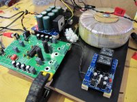
The picture shows the case with PSU, Amp, DC-Protection (actually not connected) (Sorry for the bad quality of work.. thats my first electronic project. I`m more a fan of speakers building and woodworking )
. While the speaker is connectect (no music runnig) i cannot measure any voltage at the outputs but the second channel without connected speaker shows dc voltage from about 3,4V DC so i think its really normal. I connected the amp board with the linear PS again (now something around 5V DC at the speaker output) and just get no sound but this ticking noise out of the speakers. The picture shows the case with PSU, Amp, DC-Protection (actually not connected) (Sorry for the bad quality of work.. thats my first electronic project. I`m more a fan of speakers building and woodworking
)Attachments
Blaukomma,
That is a nice linear PS you have there! Probably overkill for an amp like tpa3123. I am still not sure why you are running your amp at such a low voltage. The amps work better at higher voltages as you get less harmonic distortion and more power. Run them between 12v and 19v and the easiest thing (and much more compact and cheaper) is to use a SMPS brick from a laptop style power supply. A cheap one for $8 that puts out 19v at 3.4 amps will work fine. I wonder if the clicking is because you are running at such a low voltage below rated value. Most people never go below 12 volts.
Try 12 volts or more.
Then try the YJ Blue TPA3116D2 amp next ($20). It is a newer TI amp that has more power and sounds better.
Last edited:
Hey xrk, i think you misunderstood me. I'm using the 6,8v just for testing the amp board because, it always worked with this Power supply. The psu on the picture produces 22v Dc and this is the one i want to use for this amp. But it seems I'm connecting it wrong or it has a Problem... But i Do Not see any mistakes by connecting - with - and + with +.. I will upload a picture with the circuit Diagramm and a picture of my connection between those boards. Maybe i'm just blind and missed an obvious mistake.. Thanks for you help!
I will upload a picture with the circuit Diagramm and a picture of my connection between those boards. Maybe i'm just blind and missed an obvious mistake.. Thanks for you help!You need to make sure the power supply you have is not a dual rail +22v and -22v supply as that would be 44 volts and blow your amp. If it is +11 and -11 then that won't work if the ground on the power supply and amp are referenced to same common ground. I only say this because I see a nice toroidal transformer (markings show dual 15v output coils) and full wave bridge rectifier with lots of caps. Usually a sign of a dual rail power supply. Perhaps you are only using half of the supply? The TPA amps are single rail power supply only.
Last edited:
- Status
- This old topic is closed. If you want to reopen this topic, contact a moderator using the "Report Post" button.
- Home
- Amplifiers
- Class D
- Sure Electronics TPA3122 amp power supply