Why not just an RC as I suggested earlier ?
No need for switches.
I would also put a diode across the resisitor to discharge the capacitor on power down.
An externally hosted image should be here but it was not working when we last tested it.
Hi,
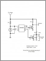
Just to show how easy it is done using a micro attached it is an schematic showing the way I will implement it using the Nano8.
Also here it is the program use to control the mute and the shutdown.
Nothing to it. Also this can be use to control any amplifier start up.
'This program will control the mute and the shutdown
'At the turn ON of the amplifier
Main
High P0 'Enable shutdwon by applying 0 volts to the shutdown pin 2.
low P1 'Enable mute by applying 2 volt to the mute pin 3.
Pause 10000 'wait for 10 seconds to allow the PS to settle
Low P0 'disable the shutdown by ampplying the rail voltage to the shtdown pin 2
high P1 'disable the mute by applying zero volt to the mute pin 3
stop
Attachments
An externally hosted image should be here but it was not working when we last tested it.
You don't have pin 2 (SD) shutdown connected to anything here. SD needs to be held high (greater than 2 volts) a couple of seconds after power is applied to Vcc. I agree no switches if you use a diode or resistor to drain capacitor. Your 10 uf and 10kOhm time constant is only about 70 msec, is that long enough for SD circuit to latch while power stabilizes?
Here is a sketch (sorry it looks so bad, all i can do on android tablet).
Attachments
Last edited:
Nigel,
I'm not understanding what you did. Could you give me a sketch and do you mean by "PIC", a printed integrated circuit?
<snip>
Mark
A PIC is a microcontroller with built in A-D and D-A conversion. He's using it to give it some 'smarts' - watching when power is good and so forth. There are a tremendous number of possibilities when adding a computer to the project. If it sounds like overkill it actually isn't and you'll find a bunch of things you may have thought about but didn't bother with because discrete logic can turn into problems as well and what's worse, logic gets corrected with 'cuts and jumpers' whereas logic errors in your controller just get erased and re-programmed. The same controller can also be used for remote control and other interfacing.
G²
Thanks for your offer
Hi,
Thanks for your offer regarding the basic micro. I wouldn't have the foggiest notion how all that is done. I will take you up on it unless an easier solution can be found, like the resistors and diode suggestion.
I'll be using 24VDC when that power supply arrives. But right now the one I'm using runs about 18.4 (with no load).
I can measure the voltage on those pins if needed. Set meter to DCV, correct?
So, please stay tuned!
Mark
Hi,
In the schematic the shutdown pin 2 it is connected to the + voltage means that the shutdown it is disable. Zero volts means enable. The mute pin 3 it is connected to ground. Zero means that the mute is is disable. 2 volts means that the mute it is enable. How much voltage your are using in you PS? I may come up with a schematic using the basic micro. I can make the circuit using the micro basic nano 8 if you are interesting. I will programming it for you. It is a simple program.
Hi,
Thanks for your offer regarding the basic micro. I wouldn't have the foggiest notion how all that is done. I will take you up on it unless an easier solution can be found, like the resistors and diode suggestion.
I'll be using 24VDC when that power supply arrives. But right now the one I'm using runs about 18.4 (with no load).
I can measure the voltage on those pins if needed. Set meter to DCV, correct?
So, please stay tuned!
Mark
This problem must have an easier solution than the complicated schemes with external parts and programming. ......................................................................................................................
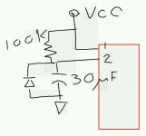
EDIT: You can skip the 3-pole switch by putting a couple of 1 Meg ohm resistors in series to the positive electrolytic cap terminal to drain it to ground slower than the 100 k ohm charges it (20 x in this case). Then it is all passive.
xrk:
I sure hope you are right and this could be solved with a couple resistors. As I understand you, it would be (2) say 1/4 watt 1 megaohm resistors attached from lug 2 of the chip to the positive lug of C12?
Thanks,
Mark
Hi,
Your are welcome any time if you decide to use my circuit design. You can built it in small circuit board. Parts are available in any Radio Shack store and you can buy the micro from Basic micro. We can exchange micro once I programmed it. I have some spares Nano 28, Nano 18 and Nano 8.
Your are welcome any time if you decide to use my circuit design. You can built it in small circuit board. Parts are available in any Radio Shack store and you can buy the micro from Basic micro. We can exchange micro once I programmed it. I have some spares Nano 28, Nano 18 and Nano 8.
Hi,
Your are welcome any time if you decide to use my circuit design. You can built it in small circuit board. Parts are available in any Radio Shack store and you can buy the micro from Basic micro. We can exchange micro once I programmed it. I have some spares Nano 28, Nano 18 and Nano 8.
Tauro
Thanks, well, I'm not entirely certain I understand your circuit there in post #22 right now, but we can clarifiy that later if need be.
I'd be inclined first to try the simple solution with resistors (if I am understanding XRK correctly).
If that doesn't work, I guess the Nano 8 it is. I'd appreciate your help if it comes to that, yes.
Oh, I don't about getting parts for your circuit at Radio Shack. Seems like everything I need I have to mail order. Radio Shack seems pretty useless anymore.
You need $4 worth of parts and it costs $12 to ship them. That, and being over my head is what I dislike about this hobby. What I like about it is fellows like you jumping in to help when that happens!
I'll let you guys decide what the best solution is. It's beyond me. I'm just a rookie kit building who barely undestands what's going on. I know a lot more than I did four or five years ago so I'm trying. But programming microchips and putting together breadboard circuits is biting off a lot for me. I'd give it a go of course, but with someone looking over my shoulder so to speak.
Regards,
Mark
sketch in post #23
XRK
Oh, I see what you mean. The sketch in post #23 is what you suggest.
On that schematic, what sort of diode do I need and I may need clarification of where the power (I think you marked it VCC) physically is located on my Jerry's Amp. I have some spare diodes in the parts bin. I can get you the numbers.
So, a cap, resistors, some sort of diode, attached to pin 2 of the Texas Instruments chip.
I'm thinking of the best way to physically hook this up. Jumper wire from that pin 2 I suppose. Everything is very small. And a separate breadboard for your ciruit?
This is the first thing I've ever built using a chip, so pardon my ignorance and lack of experience please.
Mark
xrk:
I sure hope you are right and this could be solved with a couple resistors. As I understand you, it would be (2) say 1/4 watt 1 megaohm resistors attached from lug 2 of the chip to the positive lug of C12?
Thanks,
Mark
My sketch in post 23 shows how to connect it, but I am not sure I did the diode correctly. I know if you put two 1 Megohm resistors in series where the diode is it should work. You need 100 kohm, 2 x 1 Megohm, 1 circa 30 microFarad 35 volt electrolytic capacitor. Connect them as shown between pins 1 and 2 with Vcc on pin 1 and ground on the negative of the capacitor and the two 1Mohm resistors. Basically, it is a 2 second timer circuit to allow the amp to stabilize before allow the shutdown SD input to go high logic. Vcc is your positive power supply rail.
Good luck.
Last edited:
Let's see if I understand this
XRK
I printed out your circuit and thought about it more carefully. Let's see if I understand this. Please read carefully and see if I do.
In layman's terms, I am to:
1) Attach one end of a 100K resistor to pin#1. Other end to pin #2.
2 On the resistor lead, at the pin #2 side, solder the negative end of a 30uF (what voltage?) capacitor.
3) Run the positive lead of that capacitor to a ground. (Question: Where is this ground? Note that I am using a wooden enclosure.)
4) A diode jumps/parallels the capacitor. The striped end of the diode attaches to the negative of the cap, and the other end of the diode also attaches to the ground.
Can this ground point simple be a screw driven into my case/enclosure?
Am I understanding it?
Thanks,
Mark
XRK,
Looks like you posted while I was writing #33.
So, everything the same (and as I understand it)?
Only thing is substitute (2) 1Meg resistors in place of the diode?
Mark
The positive lead of cap goes to pin 2, neg to ground. 2 x 1 megohm res connect to pin 2 and to ground. 100k res from pin 1 to pin 2.
Last edited:
Thanks!
Hi,
Sounds easy enough. I'll try it when I get a cap.
I just got a note from Jerry of Jerry's Electronics. He says he's been playing with pretty much the same circuit and I take it it helps, but not quite to his liking yet. So, I guess we'll see what he comes up with.
He mentioned I'd have to break a trace between pins 1 and 2. Must be he's got them connected on his circuit board.
I appreciate your help very much. Looks like I had the cap + and - markings mixed up in my head. Better go back and consult my basic electronics notes!
Thanks,
Mark
The positive lead of cap goes to pin 2, neg to ground. 2 x 1 megohm res connect to pin 2 and to ground. 100k res from pin 1 to pin 2.
Hi,
Sounds easy enough. I'll try it when I get a cap.
I just got a note from Jerry of Jerry's Electronics. He says he's been playing with pretty much the same circuit and I take it it helps, but not quite to his liking yet. So, I guess we'll see what he comes up with.
He mentioned I'd have to break a trace between pins 1 and 2. Must be he's got them connected on his circuit board.
I appreciate your help very much. Looks like I had the cap + and - markings mixed up in my head. Better go back and consult my basic electronics notes!
Thanks,
Mark
Oh, so it is a known usual problem with Jerry's circuit? Glad I wasn't crazy for thinking of this circuit. Play around with the value of the 100k res or the cap if it doesn't have a long enough delay to do the job. Yes, cut the trace between 1 & 2 with an xacto.
Good luck.
X
Good luck.
X
Yes, known problem.
Oh yes, it's known because I've been writing to Jerry since I put this together last week. I'm not sure how long this amp's been around. Maybe not all that long.
He said he was working on something, but you know how that goes. Might happen. Might not. So I thought I'd ask you fellows. This snap turn-on thing seems to be a common problem with what I'll call generically chip amps (I'm not sure of the technical differences between D, Tripath, chip amps) ....and I figured in 2013 this was pretty much a worked out non-issue in the development of chip chip amps. I never considered this thing would snap at me like that when I order the kit.
In the letter I got from Jerry last night he was messing with a much larger cap.
I think it's a solvable problem. And the amp is nice enough to warrant some work on it.
Mark
In the letter I got from Jerry last night he was messing with a much larger cap.
Mark
I double checked my math and it also depends on how many volts you are driving it with as that affects how fast the cap charges up to the 2 volt logic level.
The equation for the voltage at a capacitor in an RC circuit is:
Vc = Vsupply x (1 - exp(-time/RC))
rearrange and solve for C we get
C = -time / [R x log(1-Vc/Vs)]
So assuming you are using a 12 volt power supply, Vc is 2 volts, time is 2 seconds, and R is 100 k ohms, solve for C to get
C = -(2 sec) / [100000 ohms x log(1-2/12)] = -2 sec / (100000 ohm x -0.182) = 110 micro Farads
So something bigger than 110 uF should work. Of course if you are using a 24 volt supply, you need to double the capacitor size.
I am in process of building my TPA3118 and may run into same issue so glad I am looking at it now...
Good luck.
X
Hi there X,
OK, I am currently running 18.4VDC ( measured with no load), but soon will be running 24VDC when that supply arrives. So 220uF or better it is for a cap. I just checked my e-mail and that's the exact value Jerry was playing around with.
Tell me about the amp you're building. Is it your own design or a kit. If a kit, point me towards it.
Thanks for your continuing help.
Mark
- Status
- This old topic is closed. If you want to reopen this topic, contact a moderator using the "Report Post" button.
- Home
- Amplifiers
- Class D
- Power up - loud snap