Then a piezo tweeter defeats the laws of electricity. (i.e. the laws of Ohm in Z )
1Mohm is usually not what we're talking about in this context. A series resistor of sufficient size will naturally attenuate a piezo, however for all common values, ie. below 200-300 ohm, it will not. At least not audibly.
I however forgot to note that it is imperative to NOT use power resistors but high quality metal film or even better carbon composition resistors. Power resistors are wire-wound and have parasitic inductance. Even Vishay/Dale "non-inductive" resistors have enough parasitic inductance to audibly adversely affect sound quality.
With a 47 ohm series resistor in series with a 0.13uF piezo in parallel over 8 ohm woofer on a 16Wpeak amp will only require a 0.25W resistor in worst case scenario, so there is absolutely no need for higher power tolerance resistors.
Dear ataudio, I think you are mising the point.Then a piezo tweeter defeats the laws of electricity. (i.e. the laws of Ohm in Z )
I agree that such tweeter can be modeled better like a capacitor, and a capacitor (i.e of the same value) in series of will make a more or less fully capacitive partitor, with more foresable effects on phase. But a series resistor *will* attenuate it of as much you want. Try with 1 MOhm.
An "attenuator", by definition, "attenuates" smoothly across all the range of frequencies to be reproduced.
In the case of a Piezo Tweeter, if it has a smooth frequency response from, say, 3 KHz to 20 KHz at, say, 94dB SPL, and it's "too loud" to match a driver with, say, 91 dB SPL , the goal should be to pad it evenly across its frequency range.
Being "a capacitor", the proper attenuator is also a capacitor, which will form a capacitive divider and work evenly as intended.
On the other side, a series resistor will form something very different, a low pass filter.
Yes, it will "attenuate", sort of
 , but in a useless way.
Too little at low frequencies; unusably too much at high frequencies, with a 6dB/Oct slope.
Who wants that?
It's not the intended goal by any means.
Ok about the piezo resistor idea, where did you get that value from, and what kind of response shaping will it have? I am going to buy good quality resistors etc. from Solen here in Canada, but now I am unsure on the values. I was already planning on using a 6.8 air inductor to LP the woofer around 3khz.
Ok about the piezo resistor idea, where did you get that value from, and what kind of response shaping will it have?
Listening tests. There's no audible response shaping in the audible range even at 100 ohm series resistor, ie. it is less than 1dB. There will however be phase issues in the audible range. These are actually subjectically beneficial to the high frequency response of a piezo but only within certain undocumented limits. I'll leave that to people with more spare time on their hands to figure out if there is an optimum amount of phase change.
You don't need to buy brand name resistors. Any quality 20 cent resistor will do. I suggest buying 2 resistors of 47 ohm each for each piezo. Then you can experiment with 3 values, 23 ohm (in parallel), 47 ohm (one used) and 94 ohm (in series) to see which value you prefer.
People that have a preference to electronica music often like the harsher sound of 23 ohm. And people that prefer acoustic music often like the very soft sound of 94 ohm. I prefer the middle of the road option.
Ok, thank you.
Do you not agree that to run a -6db bafflestep, to keep driver efficiency, I should be running active if doing so?
I want to add that I just used the baffle diffraction simulator, and if I roll the edges by 1/2 inch, with my current box design, I am at +3db 100hz, -6 at around 60hz, and generally around 0-2db the rest of the way. Am I missing something by you saying it is going to be -6db?
Last edited:
Ok about the piezo resistor idea, where did you get that value from, and what kind of response shaping will it have?
"Soft" , "harsh" , are better than nothing descriptions, but in this case, the -3dB point for a Resistor and a 0.13uF capacitor (typical Piezo) is easy to calculate.Listening tests. There's no audible response shaping in the audible range even at 100 ohm series resistor, ie. it is less than 1dB.
As in:
100 ohms ... 12 KHz ... well within the audio range.
47 ohms .... 24KHz ... outside audible range, so can be considered "flat", at least by ear.
23 ohms .... 48 KHz ... only bats will notice.
Ok, thank you.
Do you not agree that to run a -6db bafflestep, to keep driver efficiency, I should be running active if doing so?
I want to add that I just used the baffle diffraction simulator, and if I roll the edges by 1/2 inch, with my current box design, I am at +3db 100hz, -6 at around 60hz, and generally around 0-2db the rest of the way. Am I missing something by you saying it is going to be -6db?
Baffle step and diffraction aren't the same thing. What I'm saying is that if you use your speaker outdoors you lose the room enhancement of bass. That will make it sound thin if you're using a standard tuning. It is important to note that it in my opinion is not possible to build a speaker suitable for outdoors use and for the use that most people relate to as a boombox without it being a bipolar speaker.
Oh, and yes, baffle step compensation should be made electronically. Not passively in the speakers. Bipolar speaker do not ever need baffle step compensation.
Last edited:
"Soft" , "harsh" , are better than nothing descriptions, but in this case, the -3dB point for a Resistor and a 0.13uF capacitor (typical Piezo) is easy to calculate.
As in:
100 ohms ... 12 KHz ... well within the audio range.
47 ohms .... 24KHz ... outside audible range, so can be considered "flat", at least by ear.
23 ohms .... 48 KHz ... only bats will notice.
In my defense I'm 40 yo. And by that standard i have very excellent hearing (especially for a long time guitar player), yet I can't hear crap over 14-16Khz, and my hearing is limited from about 10-12Khz. In the latter respect I'm very much like most other mature adults.
And I did say it was my subjective opinion
Last edited:
Here's a technote on piezo's and resistors
Pulsar Developments Ltd - Piezo Tweeter Application Note
Hope this helps
Pulsar Developments Ltd - Piezo Tweeter Application Note
Hope this helps
Here's a technote on piezo's and resistors
Pulsar Developments Ltd - Piezo Tweeter Application Note
Hope this helps
Thank you I have read, and will continue to read more. I am a little distraught at why Saturnus is saying it will sound absolutely terrible though
, even though hundreds of boom-boxes are designed the same way with much less sensitive speakers on much smaller baffles. I am not expecting to play techno and rave music, so bass is not a priority.Thank you I have read, and will continue to read more. I am a little distraught at why Saturnus is saying it will sound absolutely terrible though
Don't think I've said it would be terrible. It will just be similar to all those boomboxes you refer to. The Boominator is just designed to much higher standards. That is all.
Dear saturnus, I as not criticizing you at all, but providing some Math to clarify the discussion.
None taken. I don't think the math is entirely accurate though as it doesn't really fit with measurements. A piezo isn't a purely capacitive load, it has a fair amount of both series and more significantly parallel parasitic resistive elements.
Don't think I've said it would be terrible. It will just be similar to all those boomboxes you refer to. The Boominator is just designed to much higher standards. That is all.
I have understood now what you were talking about with your design. The idea is that identical drivers playing at equal magnitudes will curve around the box, meet somewhere in the middle almost, and create a sort of infinite "wall", which simulates a massive infinite baffle, thus almost completely correcting for baffle loss.
6db is a ton of attenuation so I am very interested to hear how my box is going to sound. If it doesn't sound well, the drivers were $20 each so I will pick up a couple more and remake the box, it is that simple.
I do appreciate your help, however you don't have to be arrogant about the fact that your design was built to "higher" standards. You spent considerably more money than I have, and are doing it to achieve different goals.
Also worth mentioning, I am going to alter the height and compress the depth as much as possible to maximize the surface area of the front baffle, to lower the frequency as much as possible.
Last edited:
I used SketchUp. I had NEVER used any CAD software or Sketchup or anything before yesterday, and I learned in a few minutes how to figure it all out, you will be ok Trimble SketchUp it is free also.
I had to make like 4 revisions because I couldn't fit the piezo's on the front panel piece properly.
I have Lipo chargers and a few 11.1v Lipo's hanging around from my electric R/C however I prefer that SLA's are cheaper, and also have that perfect voltage to sit at. An 11.1v pack is a little low for voltage, and a 14.8v pack is a little high so...yeah. Ni-MH is an option also, but obviously more expensive. I mean, I am paying $55 CDN shipped to my door for 18Ah of juice, hard to argue with that.
I'm looking to do something similar, a battery powered, solar charged, decent sounding, INEXPENSIVE outdoor boombox. In my experience, LiPo batteries are typically packaged in a 3-cell arrangement, providing 12.6 VDC (4.2V x 3) at full charge. I've gotten them through AliExpress (China), relatively cheap, around $19 USD for 6.8AH 12V units about the size of a pack of cigarettes, of the "100's" type. LiPo's for CCTV or radio controlled toys are typically 12.6V. They are much smaller and lighter than SLA's
Those batteries allow me to power an amp with either 12V or 24V, although I haven't settled on an amp yet. The batteries are charged through a simple charge controller and 10W solar panel(s). Monocrystalline panels are used because they provide more power per surface area than polycrystalline (or multi-crystalline), and they still produce power under an overcast sky or not in an optimal position in relation to the sun. If using LiPo batteries, be careful to use a solar charge controller designed for LiPo's, as the charged voltage is different than an SLA and overcharging a LiPo will explode it.
Last edited:
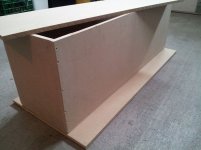
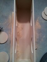
Ok so the box is almost done. The cuts from the Lowes near me were ATROCIOUS!! All the sides had overhang, or underhang, some up to 4mm!!! on 12mm wood. Anyways.
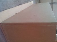
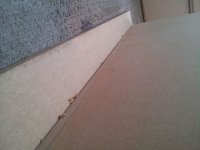
I sanded all the joints dead equal, and spent some time smoothing all the corners except for the top piece, which I am going to allow to be removable. A little more sanding left, then paint. The colour I chose is Tree Frog Green, with valspar's signature hd colour paint (was 2 for 1 this week)

The box is narrower to allow magnet to magnet mounting, however I am not going to split the chambers after all. Without the middle enclosure, I can get enough space for 0.5-1db of extra output @ 100hz from a larger enclosure volume.
Solar panels, I originally purchased a 10w poly, but have since cancelled and purchased (4) 5w mono PET laminated panels. I am going to use 3 of them to recharge the battery, and one specifically for USB devices during sunlight hours.
I sanded all the joints dead equal, and spent some time smoothing all the corners except for the top piece, which I am going to allow to be removable. A little more sanding left, then paint. The colour I chose is Tree Frog Green, with valspar's signature hd colour paint (was 2 for 1 this week
)
The box is narrower to allow magnet to magnet mounting, however I am not going to split the chambers after all. Without the middle enclosure, I can get enough space for 0.5-1db of extra output @ 100hz from a larger enclosure volume.
Solar panels, I originally purchased a 10w poly, but have since cancelled and purchased (4) 5w mono PET laminated panels. I am going to use 3 of them to recharge the battery, and one specifically for USB devices during sunlight hours.
Attachments
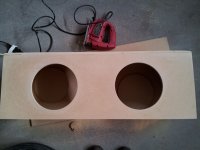
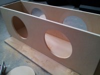
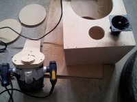
Ok I just spent a couple hours cutting out all the required holes, EXCEPT for the 3" port's on the sides (since I don't know exact O.D yet, I want to be precise). I got all my measurements within half a millimeter so I am pretty stoked.
Next step is to fill the screw holes and any slight variations with filler and then sand to make the surfaces smooth. Then router out the port holes, then paint.
Next step is to fill the screw holes and any slight variations with filler and then sand to make the surfaces smooth. Then router out the port holes, then paint.
Attachments
- Status
- This old topic is closed. If you want to reopen this topic, contact a moderator using the "Report Post" button.
- Home
- Amplifiers
- Class D
- Building (2) 10" Portable System, parts purchased