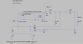
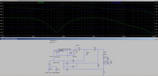
INSOD - INverting - Self - Oscillating - class D. A nice little idea for a class-D amplifier. Note the simple adaption to deadtime at Q16, 18, 19. And look to the output filter ")
The drive signal for the Mosfets still looks bad, so the dips.
But anyway, this circuit has a lot of potential.
- Inverting mode
- Self oscillation
- Negative feedback regulates the filter
- Very simple
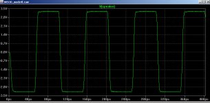
Output:
The drive signal for the Mosfets still looks bad, so the dips.
But anyway, this circuit has a lot of potential.
- Inverting mode
- Self oscillation
- Negative feedback regulates the filter
- Very simple
An externally hosted image should be here but it was not working when we last tested it.
Output:
An externally hosted image should be here but it was not working when we last tested it.
Hi Iacob,
this is the asc-file for LT-spice
INV-class-D.asc.zip
I think, I will take a chip like IRS20124 or something and a fast comparator.
Regards Patrick
this is the asc-file for LT-spice
INV-class-D.asc.zip
I think, I will take a chip like IRS20124 or something and a fast comparator.
Regards Patrick
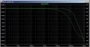
This is the bandwidth at a simulated speaker.
Green - Voltage
Blue - Current
Green - Voltage
Blue - Current
An externally hosted image should be here but it was not working when we last tested it.
Absolutely great to see that you are rolling your own design.
Hm, adaptive dead time. To me it looks like this arrangement is more an self adaptive guarantee for heavy shoot through peaks (not checked your sim up to now).
Also I think your upper gate drive cannot provide voltages above the supply rail and consequently the upper MosFet will operate in linear mode with large voltage drop from drain to source.
Q4 will most likely run into saturation and consequently will need ages to switch off again.
Looking for a level shifter with gate drivers is a good choice.
I am curious about your findings with IRS20124.
IRFP240 is not a fortunate choice. Poor body diode.
Besides the IRFP240 being a poor candidate even in the 200V range, it is never a good idea to use MosFets with unnecessary high voltage ratings in classD, because the body diodes generally become worse and worse with increasing voltage. Less critical, but unpleasant as well are the increasing Rdson and increasing gate charge the higher you chose the voltage rating.
In your voltage range you can find lots of MosFets with good or even great body diodes. I.e. IRF540Z.
So far I have not seen a circuit that uses the output filter in this way.
I publish all my spontaneous ideas to prejudge patents. Because I am against big companies to apply a patent for any nonsense.
Without the adaptive dead time I have heavy shoots. But the circuit is quick and dirty and it is well possible thats the adaptive dead time produce faults. It's too simple
The IFRP240 is only for simulating the idea of the circuit(it is the rest of an other existing circuit, I was to lazy to draw it new... )
I still have a few IRFB4212 from my experiments with the IRS2092 and I will take them for testing in reality... maybe, when I find time
I publish all my spontaneous ideas to prejudge patents. Because I am against big companies to apply a patent for any nonsense.
Without the adaptive dead time I have heavy shoots. But the circuit is quick and dirty and it is well possible thats the adaptive dead time produce faults. It's too simple
The IFRP240 is only for simulating the idea of the circuit(it is the rest of an other existing circuit, I was to lazy to draw it new...
)I still have a few IRFB4212 from my experiments with the IRS2092 and I will take them for testing in reality... maybe, when I find time
At least to me - it has an unique touch.So far I have not seen a circuit that uses the output filter in this way. (
Key questions would be modulator distortion and frequency drop at high modulation levels. Frequency seems to drop pretty much.
Sounding reasonable.I still have a few IRFB4212 from my experiments with the IRS2092 and I will take them for testing in reality... maybe, when I find time
Hint before you step into layouting:
Simulate a high load situation of your switching stage including PCB track inductances.
Already without detailed calculation of the tracks, you can just put a few nH for every track of your PCB. Simulation results will be eye opening to which tracks and loops and snubbering you should pay special attention.
...played a little bit with parameters and would recommend a faster filter
and larger D portion in the feedback in order to get acceptable step responses.
Attached my SIM file.
Starting to like your modulator.
It is naturally leading to high loop gain, similar like UcD
Consequently the shape of the carrier turns triangular without needing further tricks and you can expect very good distortion figures of the modulator.
But it also suffers from similar downsides like UcD.
Switching frequency is extremely depending from the delay times.
For reasonably low fs you might have to add delay on purpose.
If you set delay times which fit to the nature of the IRS+MosFets you will get pretty high switching frequencies.
Also like UcD it is hard to parametrize for a small frequency drop towards high modulation levels.
...well, and of course you could always complicate it with additional dynamic hysteresis and gain stage in or higher order loop structure in order to overcome all this, but you would loose the charm of simplicity.
I think it is worth to keep it as simple as you had put it there and see to which level of performance you can bring it in reality. Not just from measurements, but also in terms of sound.
Attachments
Hello people,
I've played with LT-Spice on my amp and would like to share the results with you. Thanks chocoholic who showed me how I can simulate the circuit, I have achieved passable results.
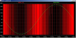
This circuit can transform easily provide a current controlled amplifier . The last graph shows a mixed circuit, voltage / current control.
I've played with LT-Spice on my amp and would like to share the results with you. Thanks chocoholic who showed me how I can simulate the circuit, I have achieved passable results.
This circuit can transform easily provide a current controlled amplifier . The last graph shows a mixed circuit, voltage / current control.
Attachments
- Status
- This old topic is closed. If you want to reopen this topic, contact a moderator using the "Report Post" button.
- Home
- Amplifiers
- Class D
- INSOD-AMP