Finally got one ClassD Professional Amplifier, PKN XD2500, for real testing into dummy load.
Those are official pdf specifications:
http://www.secozvuk.cz/download/product/00000056/xd 6000 xd 4000 xd 2500.pdf
http://www.pknc.com/XD_series_user_manual.pdf
Movies are in Romanian language, but very simple to understand , if watched movies with attention.
Dummy load resistors are 1 ohm/1000Watts, each, seried 2 by 2 to have 2x2 ohms/2000Watts dummy load.
Testing one channel only, with 4 ohms/4000W dummy load, all resistors seried:
PKN XD2500 Dummy Load 4 Ohm One Channel LECO Testing - YouTube
Testing one channel only, with 2 ohms/2000W dummy load:
PKN XD2500 Dummy Load 2 Ohm One Channel LECO Testing - YouTube
Testing both channels same time loaded each with 2 ohms/2000W dummy load:
PKN XD2500 Dummy Load 2 Ohm Both Channels LECO Testing - YouTube
Enjoy it, I left to all of you, calculations of output power, during 4 and 2 ohm/one channel also for both channels 2x2 ohm load.
To me it is acting more or less like one could expect from the data sheet.
Don't you think so?
Can you also measure the step response and show readings for the slew rate (8R, 4R, 2R)?
They ( and many others) specify 50V/us, but I usually see schematics which point to 10V/us.....
Don't you think so?
Can you also measure the step response and show readings for the slew rate (8R, 4R, 2R)?
They ( and many others) specify 50V/us, but I usually see schematics which point to 10V/us.....

I am afraid, I did not get the message of your last posting.
The power ratings seem to fit.
Clipping behavior and peak messing is also Ok IMHO.
Back regulation at continuous sine wave with 2R is also fitting to their statements. Nothing to complain.
Or did you talk about the slew rate / step response?
Basically the slew rate it is dominated by the trade off between switching frequency, amount of carrier signal at the output and amount of accepted overshoot.
As long as the switching frequency is kept reasonable (say 500kHz) and at the same time the remaining carrier residuals at the output is kept low (say 1Vpk for a power level like the XD2500) I would wonder to see step responses like 2us from -50V to +50V without excessive overshoot. Usually I would expect sloping times like 5us...10us as a reasonably good result.
Just show similar similar lovely videos or screen shots like for the power
also for the carrier residuals and large signal step response.
Even if I prefer screen shoots+text your videos are fine and indeed comprehensive even without understanding the language.
I cannot do any test because amp wasn't mine, and doesn't have it anymore for testing.
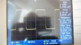
I refear at portion of first movie, where I have tested at 10 Khz in squarewave, and around 20 Khz squarewave becomes from rectangular signal to sinusoidal form.
Is exactly at min 12:40, from there till end of first movie.
I refear at portion of first movie, where I have tested at 10 Khz in squarewave, and around 20 Khz squarewave becomes from rectangular signal to sinusoidal form.
Is exactly at min 12:40, from there till end of first movie.
...these are exactly the measurements, which I meant. Sorry, that I missed them on the first run through your videos.
With an rise time of 11us and serious overshoot the results fit to normal class D technology these days.
Rise time measurement of the scope usually detects the sloping time from 10% to 90%. The rectangle was +/-70V. Means 11us from -63V to +63V.
126V/11us = 11.5V/us.
This is not a bad value, but I am wondering which measurement method will lead to 50V/us. The 50V/us appear to become a standard value in many data sheets of class D amps and it simply does not fit to what you measured and also not to what physics tells us.
Often already the L of the output filter together with the R of the speaker and the level of the supply rail limit dv/dt to levels around 10V/us, especially into 2 Ohms.
Datasheets not always reflect reality!
I saw no one to show squarewave response, on their PDF's or on presentation site...
Value are just wrotten, but very hard to be as real acting of amps.
There's an example of the last updated version, of amps modules that I sold (LECO AB Class Amp),presented here:
http://www.diyaudio.com/forums/vendors-bazaar/175365-my-500w-8r-800w-4r-ab-class-amplifier.html
I told to all mine clients that the amp module will reaches MINIMUM 40 volts per microsecond, and the printscreen is with 4 ohms dummy load.
Please be my guest and calculate slew rate of mine amplifier!
Attachments
Last edited:
Hi DJ,
your customers are free to copy my school book text from above how to calculate the slew rate and do on their own, in case they don't trust you.
I see in comparison to the measurements from the promotional thread
you have doubled the speed. Nice.
Even when talking about slew rates above, the rise times like you measured are the better criteria to judge the speed of an amp.
Required slew rate is a result of the desired frequency reproduction and desired voltage levels. Means the higher power a amp designed for the higher slew rate will be needed, while the required rise time is independent from power.
In fact already rise times around 10us are about two times faster than ribbon tweeters. Similar slowish situation like with the speakers we will find in CD players. Consequently only very slow amps will be the bottleneck in a normal sound reinforcement chain.
You are showing rise times of 2-3us and again it is up to your customers to judge how many times faster they demand the amp to be compared to their beloved snail type CD players and speakers.
- Status
- This old topic is closed. If you want to reopen this topic, contact a moderator using the "Report Post" button.
- Home
- Amplifiers
- Class D
- Testing PKN XD2500 ClassD Amplifier On DUMMY Load.