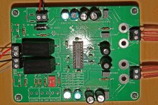
I have been trying to improve the Sure TPA3122D2 amp with the swapping out of some of the caps for others. As I am new to this sort of thing I would appreciate your comments on the changes I have made thus far:
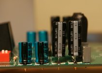
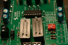
C16, 17, 19, 20 to 1uF 50V Rubycon
C7, 8, 10, 11 to 470uf 35v Nichicon
C1, 2 to 1uF 275v Panasonic film
C16, 17, 19, 20 to 1uF 50V Rubycon
C7, 8, 10, 11 to 470uf 35v Nichicon
C1, 2 to 1uF 275v Panasonic film
Attachments
Experiment with different power supply caps and values like ELna Silmic, Panasonic KA, and Nichicon Muse. It's hard to tell what you are using from your pic. Don't know what the smaller caps are there, but if they are MKP or MKT I would suggest replacing with Wima film/foil FKP.
All should be available easily from mouser.
All should be available easily from mouser.
Usually the biggest ones ") Fit New triple the UF (at least) ones or the biggest you can possibly fit, physical size being the operative limitation, for any hopes of a wee bit better bass.
Fit New triple the UF (at least) ones or the biggest you can possibly fit, physical size being the operative limitation, for any hopes of a wee bit better bass.
I'm guessing that any improvements resulted from Adding the 2 film caps.
This isn't the ideal choice amp board contraption for amazing performance potentials.
But you should certainly try, regardless.
Fit New triple the UF (at least) ones or the biggest you can possibly fit, physical size being the operative limitation, for any hopes of a wee bit better bass.I'm guessing that any improvements resulted from Adding the 2 film caps.
This isn't the ideal choice amp board contraption for amazing performance potentials.
But you should certainly try, regardless.
Thanks Bare
I'm slowly working my way up to better boards as I learn.
I am going to replace the 4 1uF 50V Rubycon caps with 470uf 35v Nichicon so they are all the same. The first mods I made were to replace all 8 rail caps (is that the right name) with the Rubycons then I changed 2 of them for the Nichicon.
cheers
I'm slowly working my way up to better boards as I learn.
I am going to replace the 4 1uF 50V Rubycon caps with 470uf 35v Nichicon so they are all the same. The first mods I made were to replace all 8 rail caps (is that the right name)
with the Rubycons then I changed 2 of them for the Nichicon. cheers
Put high quality film caps on LIN, RIN, and BYPASS (C1, C2, C14). This will be the biggest factor in improving sound quality. Replace C22 with a larger value electrolytic (100uF or so) and a small resistor (100-220 ohms) between VCC and C22. This will isolate the internal opamp stage from the switching stage.
For more bass, replace the C7/C8 and C10/C11 pairs with a 2200uF (8 ohm speaker) or 4700uF (4 ohm speaker) and make sure the power supply you plug into the board has at least double that value.
For more bass, replace the C7/C8 and C10/C11 pairs with a 2200uF (8 ohm speaker) or 4700uF (4 ohm speaker) and make sure the power supply you plug into the board has at least double that value.
Thanks guys
killerbobjr- Are you suggesting removing the1uF 275v Panasonic film caps on C1 and C2 and replacing them with new caps on L1 and L2?
How would that improve the sound over the film caps?
I am planning on using a 24v Meanwell for the ps. Is this a good choice?
cheers
killerbobjr- Are you suggesting removing the1uF 275v Panasonic film caps on C1 and C2 and replacing them with new caps on L1 and L2?
How would that improve the sound over the film caps?
I am planning on using a 24v Meanwell for the ps. Is this a good choice?
cheers
Thanks guys
killerbobjr- Are you suggesting removing the1uF 275v Panasonic film caps on C1 and C2 and replacing them with new caps on L1 and L2?
How would that improve the sound over the film caps?
I am planning on using a 24v Meanwell for the ps. Is this a good choice?
cheers
It's not clear what those caps are. It would help if you took a picture from another angle. It's difficult to see what you are already have.
The two input caps in the BOM appear to be mylar film caps. Replacing these with good polypropylene caps will improve the sound quality. The BYPASS cap (C14) is a mono ceramic. The BYPASS pin is the feedback loop bypass of the analog first stage. It definitely needs a quality polypropylene cap. I've found the change in audio quality to be noticeable.
The analog stage power supply isolation mod is a more subtle mod. The internal analog stage opamps theoretically should cancel out 100% of the power supply noise via common mode rejection. I've found this to be rarely the case. Further, the majority of the power supply noise is coming from the switching frequency of the digital output stage, which means the input stage opamps are doing the greatest amount of feedback at the output stage's switching frequency. If you think about it, the analog stage is doing the adjustment right at the point the digital stage is switching -- it's not a clean path for an audio signal. Adding a filter for the analog stage power supply reduces this potential for distortion.
The output caps (2x220uF) into an 8 ohm load roll off at about 44Hz, so increasing them to the recommended values lowers the roll off to about 9Hz, which will increase the amount of bass you'll be able to hear.
I personally would replace all those caps with the ones I mentioned earlier (muse, cerafine, silmic, etc). These TPA chips are very, very sensitive to PS cap changes and the better caps are still plenty affordable so no reason not to try them. The 1uf is a Panasonic X2? X2 are fine if you're using for AC power filtering but poor performers usually sound quality wise as input caps. Even a Solen or Bennic would probably sound better there. I also agree with earlier advice to use higher values for the PS caps.
I Agree w/ Killerbobjr.
Just my .02.
I Agree w/ Killerbobjr.
Just my .02.
Thanks for all your suggestions.
I have another question if I may:
Dumb question #2- Are the power caps and the rail caps the same thing
I think I need a Amplifier Design for Dummies book
Thanks
I have another question if I may:
What size cap would you recommend? And just C14 leaving C13 & 15 as they are?The BYPASS cap (C14) is a mono ceramic. The BYPASS pin is the feedback loop bypass of the analog first stage. It definitely needs a quality polypropylene cap.
Dumb question #2- Are the power caps and the rail caps the same thing
I think I need a Amplifier Design for Dummies book
Thanks
Rule of thumb -- make the BYPASS cap value the same as the input cap value. The input cap value should be based on your required bass cut off, which is determined by the input impedance, which is controlled by the amp gain. The minimal input impedance at the 36dB gain selection is 9Kohm, while the maximum impedance is 60Kohm at 20dB gain (all this is in the TPA3122D2 data sheet). Use the standard filter formula to determine this value:
C = 1 / (2 * 3.14 * frequency * impedance)
where 'frequency' is how low you want your bass response to be (20Hz is pretty standard), and 'impedance' is the input impedance based on the gain selected (look it up in the data sheet).
For terminology, "Power supply voltage" = "voltage rails" = "V+" and/or "V-". These all generally refer to the same thing.
I was going to order some Panasonic KA caps but not sure what to order.
My understanding is that the rule of thumb is to replace power caps with ones of the same or greater voltage. Please correct me if I am wrong. The KA's and Muse caps at 470uf are only 4v where as the ones specified for the board are 35v. Which is more important (uf or v). I was targeting 470uf because they will fit on the board.
cheers
Your power cap voltage ratings should always be more than your maximum power supply voltage. If I remember my rule of thumb with an unregulated power supply, you add a 20% margin on the maximum expected unregulated voltage for safety's sake. If you have a regulated power supply, (a 24V laptop switching supply for instance), you can use 25V rated capacitors and not worry about it.
The power supply capacitance values are based on two things: A. Ripple rejection on an unregulated supply; and B. the low frequency cutoff for your output impedance load. You need to calculate the minimum capacitance required for both. I generally like keeping the ripple to less than 1% at full load and the cut off frequency of the rails an octave lower than the cut off of the signal path, whichever is the larger capacitance value (i.e. if I calculate 100uF for a 10Hz cutoff, but 200uF for a 1% ripple, I use 200uF).
The power supply capacitance values are based on two things: A. Ripple rejection on an unregulated supply; and B. the low frequency cutoff for your output impedance load. You need to calculate the minimum capacitance required for both. I generally like keeping the ripple to less than 1% at full load and the cut off frequency of the rails an octave lower than the cut off of the signal path, whichever is the larger capacitance value (i.e. if I calculate 100uF for a 10Hz cutoff, but 200uF for a 1% ripple, I use 200uF).
- Status
- This old topic is closed. If you want to reopen this topic, contact a moderator using the "Report Post" button.
- Home
- Amplifiers
- Class D
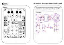
- Sure TPA3122D2 Mods