Hi all,
I have this amp to repair for a friend, it comes from England and was built in the late 80's perhaps beginning 90's.
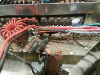
As you can see its very rudimentary but has served long years trouble free until one of the fet did explode. Its used a bass amp and has no claim to be hi-fi.
The problem I'm facing is that all the ic have been scratched off so I cant read the type they are. I tried to google for mosfet driver and look at a dozen possible replacement but didnt found a pin equivalent for U1, U2, U3, U4 and U5.
So if somebody has an idea of what they are would help alot.
I have replaced the burned mosfets but no signal at output.
U5 pin 6 is high.
U6 is CNY-742
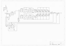
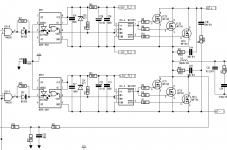
See attached schematic
This must be a self oscillating design no?
How is set the dead time?
Also U2 & U4 doesnt look to have a positive power supply? Or indirectly trough U1 & U3 ???
https://dl.dropbox.com/u/65983810/Barracuda%20amp.pdf
I have this amp to repair for a friend, it comes from England and was built in the late 80's perhaps beginning 90's.
As you can see its very rudimentary but has served long years trouble free until one of the fet did explode. Its used a bass amp and has no claim to be hi-fi.
The problem I'm facing is that all the ic have been scratched off so I cant read the type they are. I tried to google for mosfet driver and look at a dozen possible replacement but didnt found a pin equivalent for U1, U2, U3, U4 and U5.
So if somebody has an idea of what they are would help alot.
I have replaced the burned mosfets but no signal at output.
U5 pin 6 is high.
U6 is CNY-742
See attached schematic
This must be a self oscillating design no?
How is set the dead time?
Also U2 & U4 doesnt look to have a positive power supply? Or indirectly trough U1 & U3 ???
https://dl.dropbox.com/u/65983810/Barracuda%20amp.pdf
Attachments
Restart
At one time in my life I programmed in a rather cryptic computer language. Quite often I was asked to modify my own or someone else's code. The company I worked for had a policy - if you couldn't discern what the original code did within 4 hours. Then, determine what it did and write new code to achieve the same thing.
I suggest that you consider replacing the amp. Find out from your friend the wattage of the amp, then replace it with a subwoofer amp or one of the Class D amps. The new amp may not have the sentimental value, but the new amp will be more stable.
Consider that most of the electrolytic capacitors need to be replaced after 20-years. In my humble opinion, I think you would fair better over the long term to replace the amp. A repair most likely is stop gap measure.
YMMV
So true it would definitely be the easy and in the end probably the cheapest solution.
But this is a historic amplifier and has a lot sentimental value to my friend.
So I hope someone with oldscool class d technique can bring some light!
What where the gate driver used in the late 80's?
But this is a historic amplifier and has a lot sentimental value to my friend.
So I hope someone with oldscool class d technique can bring some light!
What where the gate driver used in the late 80's?
Interesting little project. Yes it really looks like it is an old DIY thing ")
U5 must be LM741 or similar single opamp
U2 and U4 must be optocouplers. Could be CNW136 I think, or similar.
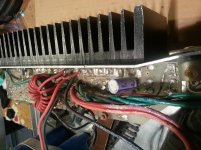
I'm wondering on why so many fets, and the big heat sink!
What is the supply voltages?
Vcc/Vss is missing on your schematic on the output.
Are you really sure the output section and coils are connected this way?
Are you sure Vdriver is not (also) connected to pin 7 and 8 on U2 and U4?
On the picture it looks like the middle mosfet has only two legs ..... meaning it is not a fet but a diode ... but maybe it just looks like this on the picture ... please check ...
Drivers could be some old IR gate drivers, but we need an update of the schematic with all supply voltages and making sure that all connections are correct, to speculate further
Best regards Baldin
U5 must be LM741 or similar single opamp
U2 and U4 must be optocouplers. Could be CNW136 I think, or similar.
I'm wondering on why so many fets, and the big heat sink!
What is the supply voltages?
Vcc/Vss is missing on your schematic on the output.
Are you really sure the output section and coils are connected this way?
Are you sure Vdriver is not (also) connected to pin 7 and 8 on U2 and U4?
On the picture it looks like the middle mosfet has only two legs ..... meaning it is not a fet but a diode ... but maybe it just looks like this on the picture ... please check ...
Drivers could be some old IR gate drivers, but we need an update of the schematic with all supply voltages and making sure that all connections are correct, to speculate further
Best regards Baldin
@ Jalejos thanks for pointing that. I have looked in the list of all published audio projects from ETI but found nothing approaching class d or switching amp. You have more details?
@Baldwin thanks for taking time. U5 can be correct, U2 and U4 can be optocouplers but not CNW136 as pin 7 & & are connected together and this wont work with a CNW 136. Another guess?
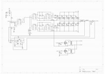
Supply voltages are +-70V, +15V relative to VEE for the low side driver and +15V relative to source of mosfets of high side.
The +-15V for the U5 is taken by 2 zener from VCC and VEE.
Are you really sure the output section and coils are connected this way?
Yes triple checked. The outputs of the Mosfets from high side and low side are separately wound each on the half of the ring core then joins together
as one wire wound around a E core.
What is the benefit of doing so?
Are you sure Vdriver is not (also) connected to pin 7 and 8 on U2 and U4?
I think you mean on U1 and U3? Triple checked too no connection between Vdriver pin7 and pin 8 on U1 and U3
About the diode its a fet. There are two diodes BYT12P but only for protection of VCC and VEE rails to ground. Not on schematic.
Below new schematic with voltages values and Vdriver psu.
@Baldwin thanks for taking time. U5 can be correct, U2 and U4 can be optocouplers but not CNW136 as pin 7 & & are connected together and this wont work with a CNW 136. Another guess?
Supply voltages are +-70V, +15V relative to VEE for the low side driver and +15V relative to source of mosfets of high side.
The +-15V for the U5 is taken by 2 zener from VCC and VEE.
Are you really sure the output section and coils are connected this way?
Yes triple checked. The outputs of the Mosfets from high side and low side are separately wound each on the half of the ring core then joins together
as one wire wound around a E core.
What is the benefit of doing so?
Are you sure Vdriver is not (also) connected to pin 7 and 8 on U2 and U4?
I think you mean on U1 and U3? Triple checked too no connection between Vdriver pin7 and pin 8 on U1 and U3
About the diode its a fet. There are two diodes BYT12P but only for protection of VCC and VEE rails to ground. Not on schematic.
Below new schematic with voltages values and Vdriver psu.
Attachments
Yes triple checked. The outputs of the Mosfets from high side and low side are separately wound each on the half of the ring core then joins together
as one wire wound around a E core.
What is the benefit of doing so?
I'd say this is to prevent/reduce shoot-through.
I had a look at the 4427 drivers which were once quite popular but their pinout wouldn't fit this one here.
What is the switching frequency of this amp ? I assume it must be quite low.
Does the manufacturer still exist ? Maybe they are willing to tell you which IC types were actually used.
Regards
Charles
U2-U4 for sure is 6N137 or HCPL2601. Gate driver could be replaced with something better, like TC4429. But 330 ohms and 5.1V zener should be added to provide 5V to Opto. With TC4429, Q6 and Q12 could be removed and R10-R26 shorted. Gate resistor should be sized to match new dead time and discharge diode added to gate resistor....
U2-U4 for sure is 6N137 or HCPL2601. Gate driver could be replaced with something better, like TC4429. But 330 ohms and 5.1V zener should be added to provide 5V to Opto. With TC4429, Q6 and Q12 could be removed and R10-R26 shorted. Gate resistor should be sized to match new dead time and discharge diode added to gate resistor....
Thanks fredos 6N137 looks like a good choice but the max VCC for it is 7 volts and only for a minute. How can this work in conjunction with U1 and U3. There is no direct supply for U4 and U2 as it is taken from pin 8 of U1 and U3. Still mystery for me!
Your solution with TC4429 looks attractive and will probably try it if I cant find the original parts. Thanks.
@ Charles no idea of switching freq but there is a input buffer before U5 not shown on schematic that makes a lowpass of about 200Hz so switching freq must be quite low.
And the builder does not live anymore so no chances to kow :-(
Also can somebody xplain me how this triple feedback network works?
Think Fredos is on the spot with 6N137. U1 and U3, bust be delivering 5V (or so) from pin 8 ..... still have no idea of what IC it is!
It's not a triple feedback network. The two signals to U6 measures signal over R17 and therefore output current, which when over a certain level will short the input signal.
But there is both a pre- (through R27)and post filter feedback (through R32||C11)... quite nice for 80's design
It's not a triple feedback network. The two signals to U6 measures signal over R17 and therefore output current, which when over a certain level will short the input signal.
But there is both a pre- (through R27)and post filter feedback (through R32||C11)... quite nice for 80's design
 Thanks Jesper this one looks like a good choice!
And the builder does not live anymore so no chances to kow :-(
He's alive and well. Someone I know spoke to him last week
How?I'd say this is to prevent/reduce shoot-through.
Regards
Charles
& Also there is no Anti-parallel diode after those two inductors, going towards the rails to snub any VDS avalanche situation arising from overshoot-undershoot at the junction of three inductors.
Last edited:
I have to admit that it doesn't look too complete in terms of snubbers and stuff.
If you just have a look at the shoot-through situation you can see that you have a series inductance between the high-side and the low side switches. Shoot through situtions usually last for only short time. During this time an inductor should be enough to keep shot-through current within reasonable limits. The devise in question actually works as an autotransfomer at this very moment.
Regards
Charles
- Status
- This old topic is closed. If you want to reopen this topic, contact a moderator using the "Report Post" button.
- Home
- Amplifiers
- Class D
- Class D amplifier from late 80's need help to repair