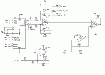
Hello, I'm planning to make a class D amp for subwoofer, and I would need to find a PWM modulator chip for it. I'm planning to use HIP4082 for driving FETs in full bridge, so I would just need to find the modulator. It's possible to make it from discrete components, but I'd prefer something easier and quicker if possible. So just asking if you have ideas what chip to use, I'd prefer something simple.
You just need a dual opamp and a comparator wired like this: http://i.imgur.com/jiG2g.png
For the second half of the bridge, just swap the high and low side inputs on the HIP4082.
The drawback with this triangular wave generator is that it cannot produce much more than around 250kHz, above that the waveforms start to distort into a sinewave.
For the second half of the bridge, just swap the high and low side inputs on the HIP4082.
The drawback with this triangular wave generator is that it cannot produce much more than around 250kHz, above that the waveforms start to distort into a sinewave.
Hmm, would this schematic be fine (first one), it would use just a dual comparator: 4QD-TEC: Pulse Width Modulators
Obviously it doesn't the level shifter, but otherwise it would seem to do the job.
Obviously it doesn't the level shifter, but otherwise it would seem to do the job.
I have never tested it and never seen anything like it used in a class d amplifier so i'd have to say no.
However the second circuit and replacing the (R6) resistor as stated with a current source, it might work, although a sawtooth waveform is not the best comparator reference waveform for a class d amp, a triangular one is whats preferred.
Sawtooth is only used in things like PWM based dimmers/DC motor speed controllers and is likely what 4QD-Tec derived this circuit from.
Ok.. however, would it be possible to modify the circuit you linked to use a single sided power supply? It didn't work (in LTSpice) when I removed the negative supply and connected the inputs of opamps that were grounded to voltage about ½ Vcc.
EDIT: Also, what's the point of Q1 and Q2?
EDIT: Also, what's the point of Q1 and Q2?
Last edited:
Q1 and Q2 in my schematic are level shifters to transform -5v/+5V swing to a 12V swing down at the negative rail.
But you don't need these with a fullbridge power stage as a fullbridge uses single supply, so ground is ground, and the triangular wave oscillator in reality works just fine on single supply with the "grounded" inputs at half the supply voltage, however you may need 10-12V single supply for the opamp to work properly.
But you don't need these with a fullbridge power stage as a fullbridge uses single supply, so ground is ground, and the triangular wave oscillator in reality works just fine on single supply with the "grounded" inputs at half the supply voltage, however you may need 10-12V single supply for the opamp to work properly.
Last edited:
Q1 and Q2 in my schematic are level shifters to transform -5v/+5V swing to a 12V swing down at the negative rail.
But you don't need these with a fullbridge power stage as a fullbridge uses single supply, so ground is ground, and the triangular wave oscillator in reality works just fine on single supply with the "grounded" inputs at half the supply voltage, however you may need 10-12V single supply for the opamp to work properly.
Yeah, it works now, apparently I messed up with the simulation earlier. Anyways, peak to peak voltage swing of the triangle wave is 1.2 volts, while amplitude of signal in line output is like 2 volts.. is this how it's supposed to be?
When the audio input is close to the amplitude of the triangle, the amp is at full power, when exceeding, the amp acts just like a class AB amp, IE clipping.
The smaller the amplitude of the triangle wave, the higher the "gain" the amp will have, especially in open loop.
Here is the actual amplifier using the circuit i posted: Improved feedbackless Class D amplifier - YouTube
The smaller the amplitude of the triangle wave, the higher the "gain" the amp will have, especially in open loop.
Here is the actual amplifier using the circuit i posted: Improved feedbackless Class D amplifier - YouTube
When the audio input is close to the amplitude of the triangle, the amp is at full power, when exceeding, the amp acts just like a class AB amp, IE clipping.
The smaller the amplitude of the triangle wave, the higher the "gain" the amp will have, especially in open loop.
Here is the actual amplifier using the circuit i posted: Improved feedbackless Class D amplifier - YouTube
Yeah, just meant that it's going to clip at quite low volume.. not that it matters necessarily.
Anyways, here's the schematic and the layout I ended up with. Ended up with HIP4081 as driver chip, as I already have them. I probably have to solder wires to some of the copper tracks to make them thicker, as there's going to be a lot of current going through.
http://koti.mbnet.fi/~jokunen_/classD_schematic.png
http://koti.mbnet.fi/~jokunen_/classD_layout.png
Last edited:
- Status
- This old topic is closed. If you want to reopen this topic, contact a moderator using the "Report Post" button.
- Home
- Amplifiers
- Class D
- PWM modulator for class D amp
