..Dimitri's comments pushed my brain to the right direction.
I am sticking to my I-want-it-all requirements and consequently will get an undesired GND loop somewhere.
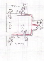
But when you wire both signal grounds to a star right at the RCA sockets, then the input amp will always automatically compensate the undesired voltage drops on the GND, no matter if used asymmetric (one RCA of each channel shorted) or symmetric.
The attached schematic shows the simplified principle without EMI filtering.
I am sticking to my I-want-it-all requirements and consequently will get an undesired GND loop somewhere.
But when you wire both signal grounds to a star right at the RCA sockets, then the input amp will always automatically compensate the undesired voltage drops on the GND, no matter if used asymmetric (one RCA of each channel shorted) or symmetric.
The attached schematic shows the simplified principle without EMI filtering.
Attachments
...did I say unavoidable loop?
Nobody heavily complaining?
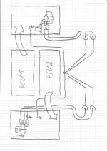
My brain blanked out the option as attached here, because I generally dislike a large geometric separation of signal wires and signal GND.
...and it messes my geometric separation of power GND and signal GND.
Fortunately my signal GND is close to the speaker power GND on the PCB and the PSU GND is not inbetween.
It will also suffer from adding to the signal the voltage drop of the GND connection between both amps, but will also benefit from the compensating effect of the input stage.
Nevertheless I am starting to think of this as a viable option, when routing the signal wires geometrically close to the GND connection.
Nobody heavily complaining?
My brain blanked out the option as attached here, because I generally dislike a large geometric separation of signal wires and signal GND.
...and it messes my geometric separation of power GND and signal GND.
Fortunately my signal GND is close to the speaker power GND on the PCB and the PSU GND is not inbetween.
It will also suffer from adding to the signal the voltage drop of the GND connection between both amps, but will also benefit from the compensating effect of the input stage.
Nevertheless I am starting to think of this as a viable option, when routing the signal wires geometrically close to the GND connection.
Attachments
V1dot5
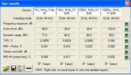
Here an update on V1dot5, which is going to be the version for my living room.
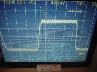
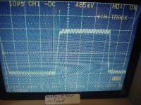
- Speed:
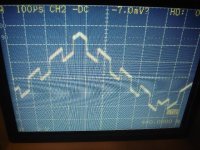
In the first two pictures you can see the amp reproducing a 12kHz rectangle with +/-10V. First without load, then with 2R load.
==> No overshoot. Sloping times of approx. 3us
Voltage scale: 5V/div
Time scale: 10us/div
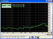
- Distortion / IMD:
See THD and IMD vs power in the table.
THD vs frequency in the graph (10W).
- Ability to reproduce complex signals with high fidelity:
AP2 often is pointing to complex music signals. Even when I doubt that you need unaffordable measurement equipment to analyse the amp with real music program - I am convinced that optimizing an amp for more complex signals pays back during listening.
A simple combination of a large triangular signal (1kHz) with superimposed rectangular signal (10kHz) can open your eyes on short comings in your design. V1dot5 showed good fidelity already from the beginning. After another analysis of the loop gain including all options to control dv/dt - the behavior of the amp brought a smile on my face.
Voltage scale: 20V/div
Time scale: 100us/div
Here an update on V1dot5, which is going to be the version for my living room.
- Speed:
In the first two pictures you can see the amp reproducing a 12kHz rectangle with +/-10V. First without load, then with 2R load.
==> No overshoot. Sloping times of approx. 3us
Voltage scale: 5V/div
Time scale: 10us/div
- Distortion / IMD:
See THD and IMD vs power in the table.
THD vs frequency in the graph (10W).
- Ability to reproduce complex signals with high fidelity:
AP2 often is pointing to complex music signals. Even when I doubt that you need unaffordable measurement equipment to analyse the amp with real music program - I am convinced that optimizing an amp for more complex signals pays back during listening.
A simple combination of a large triangular signal (1kHz) with superimposed rectangular signal (10kHz) can open your eyes on short comings in your design. V1dot5 showed good fidelity already from the beginning. After another analysis of the loop gain including all options to control dv/dt - the behavior of the amp brought a smile on my face.
Voltage scale: 20V/div
Time scale: 100us/div
Attachments
Last edited:
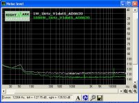
Triggered by another thread I analysed the noise and noticed that V1dot5 was wasting about 10db SNR, just by the symmetric input stage.
Unnecessary high impedances combined with LT1364 and unnecessary high gain.
So I changed to the AD8620 and reduced the impedances and the gain.
AD8620 gives one OP amp to the symmetric input gain stage and the second for the power amp itself.
Fortunately AD8620 is fast enough and provides mostly identical perfection in control, also the signal shaping for low THD remained fine.
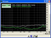
The output noise is now 63uVrms (still dominated by the symmetric input gain stage), a value which is fully up to the mark with class AB amps.
Attached a screen shot of the spectral noise distributions at 1W and 1000W.
Also THD vs. frequency remained fine.
Attached a screen shot which displays K2+K3 in comparison to THD+noise. Power was 10W into 2R.
Unnecessary high impedances combined with LT1364 and unnecessary high gain.
So I changed to the AD8620 and reduced the impedances and the gain.
AD8620 gives one OP amp to the symmetric input gain stage and the second for the power amp itself.
Fortunately AD8620 is fast enough and provides mostly identical perfection in control, also the signal shaping for low THD remained fine.
The output noise is now 63uVrms (still dominated by the symmetric input gain stage), a value which is fully up to the mark with class AB amps.
Attached a screen shot of the spectral noise distributions at 1W and 1000W.
Also THD vs. frequency remained fine.
Attached a screen shot which displays K2+K3 in comparison to THD+noise. Power was 10W into 2R.
Attachments
Last edited:
The output noise is now 63uVrms (still dominated by the symmetric input gain stage), a value which is fully up to the mark with class AB amps.
Attached a screen shot of the spectral noise distributions at 1W and 1000W.
Also THD vs. frequency remained fine.
Attached a screen shot which displays K2+K3 in comparison to THD+noise. Power was 10W into 2R.
")
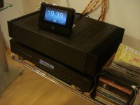
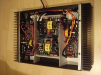
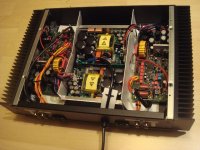
Dual mono in experimental enclosure
Why experimental?
-Heat sinks are larger than necessary.
-It is 2 units high, but 1.5 units would be sufficient.
-Wiring suffered from experimenting.
-A friend is considering to build the amp as well and go for a special enclosure, I kept the supply wiring longer than necessary in order to stay flexible for a potential transfer in a different enclosure.
Nevertheless, the set up is performing very well.
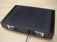
I tested both wirings (posting #422 & posting #423).
Both showed no issues with HF interactions between both channels.
The first wiring showed a slightly superior behavior in case of strong external magnetic fields. This can become relevant, when stacked directly on top of an ancient amp with monster transformers. So the wiring like in posting #422 is my final choice.
Even without top cover you can run the amp at full power without interfering a FM reciever close by.
Distortions and complex signal handling remained unchanged after implanting the amps into the housing.
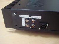
You will notice four RCAs for each chanel, two for AC coupling and two for DC coupling.
For AC coupling I am using the Panasonic ECW series. Definitely one of the better choices, when staying with non audisoteric types. The Mundorfs which I used earlier where fine as well, but with 4u7 they would simply be to large for the PCB - while the Panasonics easily compete in sound and come at attractive size.
This allows all considerable input choices:
-DC coupled symmetric inverting, DC coupled symmetric non inverting DC coupled inverting, DC coupled non inverting, DC coupled bridged.
-AC coupled symmetric inverting, AC coupled symmetric inverting, AC coupled inverting, AC coupled non inverting, AC coupled bridged.
The sound? Detailed and decent at the same time. Unmatched bass control. ...and sound stage!!
Sound stage always is a hard to meet design goal. The design variations with this amp gave me some more insights - still no bullet proof recipe.
My friend must hurry up, the more I am listening to this amp the less I want to disassemble it...
Attached some photos of the nice guy.
Why experimental?
-Heat sinks are larger than necessary.
-It is 2 units high, but 1.5 units would be sufficient.
-Wiring suffered from experimenting.
-A friend is considering to build the amp as well and go for a special enclosure, I kept the supply wiring longer than necessary in order to stay flexible for a potential transfer in a different enclosure.
Nevertheless, the set up is performing very well.
I tested both wirings (posting #422 & posting #423).
Both showed no issues with HF interactions between both channels.
The first wiring showed a slightly superior behavior in case of strong external magnetic fields. This can become relevant, when stacked directly on top of an ancient amp with monster transformers. So the wiring like in posting #422 is my final choice.
Even without top cover you can run the amp at full power without interfering a FM reciever close by.
Distortions and complex signal handling remained unchanged after implanting the amps into the housing.
You will notice four RCAs for each chanel, two for AC coupling and two for DC coupling.
For AC coupling I am using the Panasonic ECW series. Definitely one of the better choices, when staying with non audisoteric types. The Mundorfs which I used earlier where fine as well, but with 4u7 they would simply be to large for the PCB - while the Panasonics easily compete in sound and come at attractive size.
This allows all considerable input choices:
-DC coupled symmetric inverting, DC coupled symmetric non inverting DC coupled inverting, DC coupled non inverting, DC coupled bridged.
-AC coupled symmetric inverting, AC coupled symmetric inverting, AC coupled inverting, AC coupled non inverting, AC coupled bridged.
The sound? Detailed and decent at the same time. Unmatched bass control. ...and sound stage!!
Sound stage always is a hard to meet design goal. The design variations with this amp gave me some more insights - still no bullet proof recipe.
My friend must hurry up, the more I am listening to this amp the less I want to disassemble it...
Attached some photos of the nice guy.
Attachments
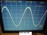
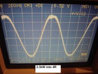
Bridged operation
No surprises.
The first screen shot shows approx. 2kW into 4R.
The output voltage of 256Vpp translates to 91Vrms, which results in more than 2kW power.
Scale: 50V/grid (1:10 probe)
The second screen shot shows 2.3kW into 4R, close to clipping.
The output voltage of 272Vpp translates to 96Vrms, which results in 2.3kW power.
Drop of fs becomes visible.
Scale: 50V/grid (1:10 probe)
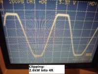
The third screen shows 2.6kW into 4R, with massive clipping.
Due to rail sagging the peak voltage is even slightly less than at 2.3kW.
Increase of power is related to trapezoidal wave shape instead of a undistorted sinusodial shape, which lifts the RMS voltage without high peak values.
Scale: 50V/grid (1:10 probe)
The measurements have been done manually with a sinusodial input signal.
The popular burst measurements with 300ms/700ms power/break would slightly lift the limits, but not much.
No surprises.
The first screen shot shows approx. 2kW into 4R.
The output voltage of 256Vpp translates to 91Vrms, which results in more than 2kW power.
Scale: 50V/grid (1:10 probe)
The second screen shot shows 2.3kW into 4R, close to clipping.
The output voltage of 272Vpp translates to 96Vrms, which results in 2.3kW power.
Drop of fs becomes visible.
Scale: 50V/grid (1:10 probe)
The third screen shows 2.6kW into 4R, with massive clipping.
Due to rail sagging the peak voltage is even slightly less than at 2.3kW.
Increase of power is related to trapezoidal wave shape instead of a undistorted sinusodial shape, which lifts the RMS voltage without high peak values.
Scale: 50V/grid (1:10 probe)
The measurements have been done manually with a sinusodial input signal.
The popular burst measurements with 300ms/700ms power/break would slightly lift the limits, but not much.
Attachments
Hi guys,
as a kind of noob in electronics I thought for a while... at the end I'm happy to have made this decision and I'm proud to have built these wonderful amps.
I was looking for a while for some potential amps to power my woofers at 2Ohm. A clean sound and lowest distortion were absolutely essential.
After several nights of soldering and some support from Chocoholic (thanks a lot!!!) we could power the amps, which had a phantastic amplified output until almost 1,3kW @2Ohm.
Although the effort is high and the amp complex, I wonder why not more people have built this wonderful amp.
I hope, Chocoholic won't loose his pleasure and will design another fine amps in the future, which he hopefully will also share with us
Regards,
Stammheim
... at the end I'm happy to have made this decision and I'm proud to have built these wonderful amps...
Again my congratulations.
It is a complex project and you made it almost free of errors!

And you helped to catch inconsistencies/mistakes in my documentation for V1.5.
I will double check again and then publish the builders pack of V1.5 .
Builders Pack of V1.5
...here it is..
...here it is..
Attachments
-
PCB_V1_Back_viewfromback.pdf131.4 KB · Views: 363
-
PCB_V1_Back_seethroughfromtop.pdf131.1 KB · Views: 394
-
PCB_V1_Front.pdf206.9 KB · Views: 468
-
SystemD_2k4_V1dot5_Supply.pdf75 KB · Views: 465
-
SystemD_2k4_V1dot_Modulator.pdf125.5 KB · Views: 540
-
SystemD_2k4_V1dot5_Power.pdf152.5 KB · Views: 637
-
SystemD_2k4_PcbVendorFiles.zip152.5 KB · Views: 412
-
SystemD_2k4_BOM_V1dot5_20140322.pdf947 KB · Views: 516
No surprises.
The first screen shot shows approx. 2kW into 4R.
The output voltage of 256Vpp translates to 91Vrms, which results in more than 2kW power.
Scale: 50V/grid (1:10 probe)
The second screen shot shows 2.3kW into 4R, close to clipping.
The output voltage of 272Vpp translates to 96Vrms, which results in 2.3kW power.
Drop of fs becomes visible.
Scale: 50V/grid (1:10 probe)
The third screen shows 2.6kW into 4R, with massive clipping.
Due to rail sagging the peak voltage is even slightly less than at 2.3kW.
Increase of power is related to trapezoidal wave shape instead of a undistorted sinusodial shape, which lifts the RMS voltage without high peak values.
Scale: 50V/grid (1:10 probe)
The measurements have been done manually with a sinusodial input signal.
The popular burst measurements with 300ms/700ms power/break would slightly lift the limits, but not much.
I feel bad for your neighbours
seriously good work, thanks for keeping the diy standards high. reminds me of eva`s work. does anyone know what happened to her ? or are the two of you working together in the silence.
Is there any method to do hysteresis control with commercial OTAs?
One of these, for example: Transconductance Amplifier * - Products - TI.com
One of these, for example: Transconductance Amplifier * - Products - TI.com
Basically it should work to take a constant hysteresis throughIs there any method to do hysteresis control with commercial OTAs?
a voltage divider from the half bridge, then gain it through such a high speed OTA and when the speaker signal comes to large levels then reduce the gain by reducing the quiscient current.
However the nonlinear Iq control characteristic will need to be taken into account.
Sadly I also lost the contact to Eva....does anyone know what happened to her ?
...would love to read of her again.
I could try to contact her via messenger. Should i?Sadly I also lost the contact to Eva.
...would love to read of her again.
- Home
- Amplifiers
- Class D
- SystemD_2kW, any interest for an open design?