I think building up the actual amp circuit is a more true to reality simulation than using the ideal voltage controlled switches and what not.
True, but similar you contradicting yourself when you build, use and publish spice models like the circuit simulations you posted in the thread.
non the less I was interested in the loop network analysis its more fun and interesting then trying to live up silicon component behaviour.
Hi Reactance,
as far as it concerns my person the boolean algebra generally delivers 'false', when checking the condition 'if you have time'.
Have a closer look to posting #375.
The LT spice simulation is already using an averaged gain modeling of the switching stage. So simulation times are short.
It can be used for AC analysis and transient analysis.
By offering this file I am disclosing lots of key informations on loop control of class D amps. Everybody can experiment with it and learn step by step.
If you want to translate it into the abstract language of linear control theory - feel free to do so, but you will loose key informations of the interactions between brute circuit non linearities and loop control (each real stage has clipping limitations!!).
Designing a classD amp with postfilter feedback, but without taking into account such fundamental non linearities, will bring you in trouble when stepping from theory to reality.
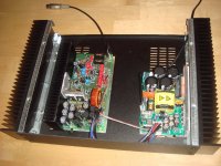
...for better listening I decided to go for a quick&dirty implant in an enclosure, which allows to use the amp in the living room.
You see I have just thrown it into the box for the moment...
In the final build I will put two half bridges properly using the outside heat sinks and two smps in the center.
Means 2x1200W @ 2R or 2400W @ 4R of high quality in a 2 unit enclosure. Short style (300mm), without fan.
But before that I have to settle my car hifi sub....
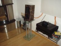
Listening chain of today:
- 8200 CDQ (CD and pre amp)
- Squeezebox Touch (Flac, MP3, internet radio)
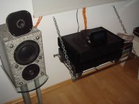
- Two different speakers
With more careful listening sessions the old battle between to different speakers came up again:
- The grey granite type offers slightly more voluminous mids and voices are slightly closer to the listener.
- The brown marble type with the ribbon tweeter from Lake West again is finally winning the game, because of lovely resolution without any aggressiveness.
The amp itself? - I designed and build it short time ago, I am afraid I am biased.
You see I have just thrown it into the box for the moment...
In the final build I will put two half bridges properly using the outside heat sinks and two smps in the center.
Means 2x1200W @ 2R or 2400W @ 4R of high quality in a 2 unit enclosure. Short style (300mm), without fan.
But before that I have to settle my car hifi sub....
Listening chain of today:
- 8200 CDQ (CD and pre amp)
- Squeezebox Touch (Flac, MP3, internet radio)
- Two different speakers
With more careful listening sessions the old battle between to different speakers came up again:
- The grey granite type offers slightly more voluminous mids and voices are slightly closer to the listener.
- The brown marble type with the ribbon tweeter from Lake West again is finally winning the game, because of lovely resolution without any aggressiveness.
The amp itself? - I designed and build it short time ago, I am afraid I am biased.
Attachments
@Tom:
...definitely overkill
Like driving a SUV or PickUp.
Fortunately the amp wastes a factor 1000 less energy and resources vs a SUV.
@Reactance:
In class AB the size would be OK 2x150W. Not for 2x1200W.
But true - the amp needs less. The heat sink as shown on page 27 in #261 is fine for my choice of short dead time and continuously driving 2R full power without forced cooling.
If less heat is desired, simply enlarge the dead time.
I like the appearance of the enclosure and oversized heat sinks are not harmful.
On the topic of heat dissipation are you able to play music at a reasonable music level without *any* heat sinking ? of course with reasonable dead time its achievable... (I like small heat-sinks makes the unit light weight and innocent similar to the look and feel of hypex modules)
(I like small heat-sinks makes the unit light weight and innocent similar to the look and feel of hypex modules)...did not try, but with long dead time it is in the nature of a class D amp to allow it...
I am aware that most friends of classD are oriented to cheap, small and low idle losses. The poor musical reputation of classD is not just a myth, its a result of lots of scrap out there.
Fortunately in my hobby I am not bound to serve this LoFi mind setting.
Converting my design?
Low idle losses you can get by long dead time. ==> Just change two resistors.
Converting it to small and cheap would be more hard.
...
The amp itself? - I designed and build it short time ago, I am afraid I am biased.
Sweet!

...hope here are not just
Nevertheless, I will have a look to the popular LoFi adjustment as well.
If a well designed amplifier class D really lives up to its efficiency of 90% >
then im sure power loss should taken into account.
I must be honest I really don't have the money to build this amplifier at the moment I was just thinking of adapting the modulator to work with a pair of IRF540Z in the mean time and a +/- 40 supply for now, not PA level power design...
Long Dead Time without heat sink
Here some measurements when you increase the dead time from 25ns to 80ns.
In short:
If 400W into 8R are sufficient and if you can live with higher distortion (still not catastrophic) then you just need the small angular piece, but no further heat sink.
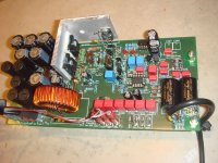
More detailed:
In the first picture you see the power devices just mounted to the angular piece.
The freewheeling diodes on the back side were without any heat sink.
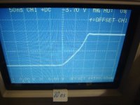
In the second picture you see the idle sloping.
Scales: 50V/grid, 50ns/grid
Dead time is 80ns. Sloping is still a slightly active forced event, but the IR chip does not offer a longer dead time.
It idles with 50C at the angular piece without heat sink.
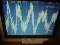
In the third picture you see the amp playing music into 8R with clipping levels of 80Vp.
This corresponds to an amp rating of 400W into 8R.
Scales: 20V/grid, 5ms/grid
No heat sink. Playing music with this level for over 1h lets the angular piece stabilize at 70C.
(I disabled the thermal shut down for this, because it would act at 65C.)
Down side of the longer dead time is the increasing distortion level, especially at medium levels.
At 10W into 2R almost nothing changes. THD around 0.008%, IMD around 0.02%.
But at 100W into 2R THD grows from 0.01% to 0.04% and IMD grows from 0.025% to 0.14%.
@Reactance:
IRF540Z is a very good choice for +/-40V.
You can directly drive it from standard level shifters and can use the body diode, instead of the intensive arrangement of my high power switching stage.
You could club together with Tekko, I think he posted an universal power stage in the 25-1200W thread.
Here some measurements when you increase the dead time from 25ns to 80ns.
In short:
If 400W into 8R are sufficient and if you can live with higher distortion (still not catastrophic) then you just need the small angular piece, but no further heat sink.
More detailed:
In the first picture you see the power devices just mounted to the angular piece.
The freewheeling diodes on the back side were without any heat sink.
In the second picture you see the idle sloping.
Scales: 50V/grid, 50ns/grid
Dead time is 80ns. Sloping is still a slightly active forced event, but the IR chip does not offer a longer dead time.
It idles with 50C at the angular piece without heat sink.
In the third picture you see the amp playing music into 8R with clipping levels of 80Vp.
This corresponds to an amp rating of 400W into 8R.
Scales: 20V/grid, 5ms/grid
No heat sink. Playing music with this level for over 1h lets the angular piece stabilize at 70C.
(I disabled the thermal shut down for this, because it would act at 65C.)
Down side of the longer dead time is the increasing distortion level, especially at medium levels.
At 10W into 2R almost nothing changes. THD around 0.008%, IMD around 0.02%.
But at 100W into 2R THD grows from 0.01% to 0.04% and IMD grows from 0.025% to 0.14%.
@Reactance:
IRF540Z is a very good choice for +/-40V.
You can directly drive it from standard level shifters and can use the body diode, instead of the intensive arrangement of my high power switching stage.
You could club together with Tekko, I think he posted an universal power stage in the 25-1200W thread.
Attachments
If a well designed amplifier class D really lives up to its efficiency of 90% >
then im sure power loss should taken into account.
Accurate measurement of efficiency is always difficult due to tolerances of the measurement equipment. Still I tried as careful as possible with my home meters and got the following results.
Set up as described above with long dead time.
Load 8R close to clipping: 91.3%
Load 8R and clipping (THD=10%): 98.1%, hard to believe.
Hi vovatver,
you will need patience, I have put your request on my backlog list during measurements on the next enhanced version.
You are asking for a lot of work:
1. Dissolder D312 & D313
2. Dismount the backplane
3. Open R222 & R216
4. Short C217 ==>disable the integrating gain
5. Resolder D312 & D312
6. Add offset adjustment and adjust it
Then doing the measurements and then reworking the amp again to the proper assembly with feedback...
I am even more reluctant to waste my time, because few postings ago it was very important to give evidence that also this classD amp acts like a normal classD amp can be adjusted for low idle losses and can run without heat sinks and has high efficiency.
For this I went through similar efforts like you are asking for - and after I posted the detailed examinations and measurements nobody did care about it.
The future enhanced version will be on the same PCB, but make use of the Infineon MosFet IPP110N20N3. ..going for an adjustment with higher fs, faster filter and faster frequency compensation ==> further improved step response.
I am even more reluctant to waste my time, because few postings ago it was very important to give evidence that also this classD amp acts like a normal classD amp can be adjusted for low idle losses and can run without heat sinks and has high efficiency.
For this I went through similar efforts like you are asking for - and after I posted the detailed examinations and measurements nobody did care about it.
Apologies Mr Chocolate
Firstly thank you for making all the effort answering most of the the time with questions we personally ask, I give you the all gratitude.. (I understand it takes time to do this, take the amp apart eveytime, remove the thermal compound, setup the scope, start the analysis process, document and reconstruct the amplifier again for listening pleasure) hopefully you wont get tired like eva, she has lost energy and patience and moved on with other priorities. (its understandable, not all of us like me here makes money off electronics its only for fun..)
Here some measurements when you increase the dead time from 25ns to 80ns.
In short:
If 400W into 8R are sufficient and if you can live with higher distortion (still not catastrophic) then you just need the small angular piece, but no further heat sink.
More detailed:
In the first picture you see the power devices just mounted to the angular piece.
The freewheeling diodes on the back side were without any heat sink.
In the second picture you see the idle sloping.
Scales: 50V/grid, 50ns/grid
Dead time is 80ns. Sloping is still a slightly active forced event, but the IR chip does not offer a longer dead time.
It idles with 50C at the angular piece without heat sink.
In the third picture you see the amp playing music into 8R with clipping levels of 80Vp.
This corresponds to an amp rating of 400W into 8R.
Scales: 20V/grid, 5ms/grid
No heat sink. Playing music with this level for over 1h lets the angular piece stabilize at 70C.
(I disabled the thermal shut down for this, because it would act at 65C.)
Down side of the longer dead time is the increasing distortion level, especially at medium levels.
At 10W into 2R almost nothing changes. THD around 0.008%, IMD around 0.02%.
But at 100W into 2R THD grows from 0.01% to 0.04% and IMD grows from 0.025% to 0.14%.
This is rather expectable levels of behaviour considering you dealing with a "programmable" DT.
@Reactance:
IRF540Z is a very good choice for +/-40V.
You can directly drive it from standard level shifters and can use the body diode, instead of the intensive arrangement of my high power switching stage.
You could club together with Tekko, I think he posted an universal power stage in the 25-1200W thread.
I decided to go the UCD route instead in favour of its simplicity (and im on a budget so optimisation and simplicity rules in favour) , diagram is from the bender post (with pole/zero compensation modifications) I haven't simulated it yet but, it seems legitimate thus far not sure for sure.
An externally hosted image should be here but it was not working when we last tested it.
[/URL]
As for the class d filter core, Micrometals cannot send me even samples cause here are no dealers and they wont ship it for free
, not a famous core but my local electronics dealer on deals with Arnold cores.(I have looked through the forum and eva recommended this)An externally hosted image should be here but it was not working when we last tested it.
Off the topic, interesting toys has reached me today as well, Analog Devices just sent me 2 AD1442 SigmaDSP Digital Audio Processor(s) (I have the SigmaStudio designer tool as well which works great and has loads of functionality !! It will put the Hypex and Mini DSP to shame
), I shall be doing some DSP stuff in this year (hopefully if time allows) for DIY DSP research should be fun. An externally hosted image should be here but it was not working when we last tested it.
Last edited:
- Home
- Amplifiers
- Class D
- SystemD_2kW, any interest for an open design?