"In my experience SMD X7R are very poor when it comes to current handling capability, you have to parallel them almost 30X in order to ensure trouble free operation when pumping multikilowatt into 2 ohms load.You haven't seen them blasting and evaporating in the air."
What about using this foil cap series?
http://www.paktron.com/pdf/Capstick_CB4.pdf
What about using this foil cap series?
http://www.paktron.com/pdf/Capstick_CB4.pdf
That's a nice offer, but not necessary.
I am generally avoiding to design in components, which I cannot get easily by regular shopping. ...so I will stick my paralleled X7R and go for double stacked in order to gain margin for reliability ...
Even without double stacking they are handling the hottrodding well up to now.
Also while working on the OCP adjustment with output currents up to 60A, they did not complain.
...sudden silence?
I guess you want to say: Stop optimizing, but release the builders package.
Ok, understood. And since the over current protection is working now as well, I think the design is mature enough to go for the builders package.
This week and coming week will be very busy in work, so I cannot promise a schedule for the builders package - but I am starting to prepare the data for V1.3.
It's a very impressive design, with impressive performance.
If I could just get my small (low watt) designs to work as good
")
Super work, Choco
Builders Package
The attached builders package already include a fundamental EMI improvement.
Earlier I mounted all Mosfets and diodes with a ceramic isolator to the heat sinks. Q309, D311 and D313 carry the jumping voltage of the switching node at their back plane and spread the RFI across the entire heat sink. Not clever.
I introduced a grounded shield between the heat sinks and Q309, D311 and D313. The shields are directly connected to GND close the switching stage.
The heat sinks are now connected by a RC to GND, 1Meg parallel 100nF.
With this improvement the disturbances of the proto open on the workbench are low enough to have just medium disturbances on my FM alarm clock while the amp is playing music at full power.
Have fun with the attached builders package.
The PCB is intended to be with 70um copper. 35um will still work, but most likely stressing some of the tracks close to melt down when running the amp in heavy duty.
Please note that this is an advanced project and employs high voltages, which can cause lethal injury.
Also regarding assembly and getting it running it is not the right project for beginners.
Looking forward to see your builds coming. I will support you in case of questions.
Attachments
-
SystemD_2k4_Supply.pdf74.6 KB · Views: 467
-
SystemD_2k4_Modulator.pdf118.4 KB · Views: 454
-
SystemD_2k4_Power.pdf150.1 KB · Views: 525
-
PCB_V1_Front.pdf206.9 KB · Views: 374
-
PCB_V1_Back_seethroughfromtop.pdf131.1 KB · Views: 317
-
PCB_V1_Back_viewfromback.pdf131.4 KB · Views: 290
-
SystemD_2k4_BOM_V1dot3_2013March10th.pdf482.6 KB · Views: 405
-
SystemD_2k4_PcbVendorFiles.zip152.5 KB · Views: 312
Some more information.
The +/-82V should be in the range +/-65V....+/-83V. It also plays at lower voltages, but it does not really make sense to run such an amp at low rails.
The +/-12V must be within +/-11V...+/-14V (can be a wall plug).
The Drv must be a floating 15V...22V connected with its minus to the -82V (can be a wall plug). For higher voltages R403 must be increased. For voltages above 25V R403 and the heat sink of Q401 must be increased.
Last edited:
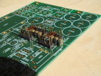
Towers of X7R
V1.3 already includes the double stacked rail caps right at the switching stage.
But I didn't have a proper picture in the Excel sheet, so I highlighted this in the BOM and the verbal description - but had to use the unstacked picture.
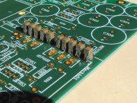
Now two pictures which show the double stacked caps.
Also the construction of the CuBars between MosFets and series diodes is shown. Ensure that the distance between the CuBars and any cap is at least 1mm.
Using the dual pin rows is making life easier during assembly and service.
If you use pin rows with a 2.54mm spacing make sure that you pull out the unused pins - not just lazzy cutting.
Needless metal parts in a high power switching stage are always a unnecessary risk.
V1.3 already includes the double stacked rail caps right at the switching stage.
But I didn't have a proper picture in the Excel sheet, so I highlighted this in the BOM and the verbal description - but had to use the unstacked picture.
Now two pictures which show the double stacked caps.
Also the construction of the CuBars between MosFets and series diodes is shown. Ensure that the distance between the CuBars and any cap is at least 1mm.
Using the dual pin rows is making life easier during assembly and service.
If you use pin rows with a 2.54mm spacing make sure that you pull out the unused pins - not just lazzy cutting.
Needless metal parts in a high power switching stage are always a unnecessary risk.
Attachments
Besides the picture, I noticed a critical thing missing in the GetItGoing part.
For the 12V operation I advise to put additional resistors of 1k8 and 3k3.
Later at higher rails I just told to remove the 3k3... Of course also the 1k8 has to be removed as well !
If you miss this, most likely the IRS20957 will be fried.
Sorry for this, hope there are no accidents so far.
I am attaching again the full updated package.
The BOM-file now contains the new picture and removal of both resistors.
All other files are unchanged.
Attachments
-
SystemD_2k4_PcbVendorFiles.zip152.5 KB · Views: 174
-
PCB_V1_Back_viewfromback.pdf131.4 KB · Views: 181
-
PCB_V1_Back_seethroughfromtop.pdf131.1 KB · Views: 194
-
PCB_V1_Front.pdf206.9 KB · Views: 217
-
SystemD_2k4_BOM_V1dot3_2013March16th.pdf521.1 KB · Views: 276
-
SystemD_2k4_Supply.pdf74.6 KB · Views: 202
-
SystemD_2k4_Power.pdf150.1 KB · Views: 235
-
SystemD_2k4_Modulator.pdf118.4 KB · Views: 312
An externally hosted image should be here but it was not working when we last tested it.

???
You seem to see even more fun in my comment, than I had planned.
I originally 'thought':
...it appears like Bruno has copied Panya's design and now Bruno is making lots of money with that, so Bruno must love Panya...
P.S.
My design is not intended for making money.
To expensive. To complex. To large.
It is intended to bring fun to DIYers and audiophile listeners.
...enough joking.
Panyahui,
I am not sure what your intension is:
Do you want to present your private build of the UcD2k? If so - nice.
Or do you want to promote business by spreading pictures of different copies in multiple threads? If so - clever, but I dislike the business model.
Panyahui,
I am not sure what your intension is:
Do you want to present your private build of the UcD2k? If so - nice.
Or do you want to promote business by spreading pictures of different copies in multiple threads? If so - clever, but I dislike the business model.
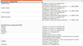
Alternative Components
The design without shaping network in the feedback of the OP amp is very forgiving regarding the OP amp requirements. Even slower types allow an acceptable operation of the amp.
Attached an overview of tested OP amps and comparators.
Since last week end I am listening to the variations - I will comment in a few days.
Also it turned out that my concerns regarding the very fast comparators were unnecessary - the disturbances on this layout and with the EMI shields are so low that even the 10ns types do not show any misbehavior.
Amazingly the SNR is even slightly better with them.
Regarding alternative parts for the power semiconductors I will go for a further build. Meanwhile the first proto is simply sounding to good - I just cannot go for mayor changes on that one anymore.
Attachments
How come this "SystemD" changed from beeing clocked to become a self oscillating topology ?
Myself i've learned to dislike self oscillating due to the switching frequency dropping as the power output increases, to me this is not acceptable, the switching frequency should remain constant from 0% modulation to 80% modulation as beyond that, propagation delay prevent further modulation, meaning skyrocketing distortion.
Myself i've learned to dislike self oscillating due to the switching frequency dropping as the power output increases, to me this is not acceptable, the switching frequency should remain constant from 0% modulation to 80% modulation as beyond that, propagation delay prevent further modulation, meaning skyrocketing distortion.
How come this "SystemD" changed from beeing clocked to become a self oscillating topology ?
Myself i've learned to dislike self oscillating due to the switching frequency dropping as the power output increases, to me this is not acceptable, the switching frequency should remain constant from 0% modulation to 80% modulation as beyond that, propagation delay prevent further modulation, meaning skyrocketing distortion.
Tekko i really thought after years being on this forum you would learn from professionally experienced people. im going to re-post this cause i don't want innocent newbies (like myself taking the advice you just posted)
Originally Posted by Eva
Here are some hints left in 2010 by eva regarding self oscillating amplifiers
Self oscillating loops have several interesting properties. For example, open loop gain is automatically compensated against changes in supply voltage, while in clocked modulators it's a direct function of supply voltage. This makes self-oscillating amplifier performance quite independent of supply rail voltage and sagging and improves PSRR dramatically.
Another advantage of self oscillating loops is that switching frequency is automatically reduced as the output approaches the rails, while keeping constant carrier residual amplitude at the output. This results in the minimum amount of switching events for a given carrier residual amplitude. In other words, switching losses are always as low as possible in self oscillating amplifiers. Switching frequency usually drops 2:1 or more before clipping.
Clocked modulators force the output stage to switch always at the same frequency, resulting in many switching events that are not really required, as the output gets closer to the rails and carrier residual amplitude becomes smaller and smaller.
Additionally, post-filter self-oscillating recycles the extra gain due to filter resonance as open loop gain, thus reducing output impedance (and THD too). In other words, the filter can resonate close to 20khz or even at a lower frequency without compromising frequency response.
Once you have put together a prototype which takes advantage of all this (and more), you don't feel like going back to clocked modulators.
Quote:
Originally Posted by Eva
Your main misconception about PWM amplification is assuming that a non-constant switching frequency results in non linearity.
The absolute minimum switching frequency is 2 times the maximum frequency you want to amplify, 44Khz for 22Khz audio.
The main reason for using 10 times higher frequencies (400Khz) is being able to deal with carrier residual with a 12db/oct output filter.
In clocked modulators carrier residual amplitude is maximum near 0V output and drops to 0 when the output approaches the rails (ugly looking waveform btw). Carrier residual amplitude is modulated by audio signal.
In self-oscillating modulators carrier residual amplitude is almost constant and frequency is smoothly reduced to keep it constant. There is no penalty, it just takes advantage of a "feature" of the output filter that you can't use with a fixed clock.
This reduction in switching frequency does not involve any reduction in the amount of negative feedback, so linearity is unchanged.
Another advantage of variable switching frequency is spread spectrum EMI. Variable switching frequency is now being used in many SMPS control ICs. I nearly always use it in clocked modulators too, for example in PFC.
Well i do not like the reduction in switching frequency as power increases as it reduces resolution at higher frequencies. The only reason i can think of that ppl prefer self oscillating despite the switching freq drop is that during the power sucking transients, the highers frequencies are already sidechained(lowering the volume of other instruments during the duration of the kick drum) meaning the effect of the drop in switching frequency is hard to notice as its virtually impossible to cause much if any change in switching frequency at the treble range without going deaf as it takes pretty much earphone power levels to bring a tweeter to ear bleeding levels.
Some ppl on this forum have made up their mind though that 400kHz is nowhere even near enough switching frequency to allow an amp to be called hifi, but rather having to be 1MHz and beyond, which increases switching losses and EMI.
BD modulation solves this as a fullbridge approach virtually quadruples the switching freq, meaning a 250kHz switching freq at the fets still gives the same performance/resolution as a 1MHz single ended class d, unfortunately BD modulation cannot be achieved with a self oscillating topology as the output carrier residual is zero at idle, bringing back the so called disadvantages of clocked class d.
The BCA topology is another way of getting away with a lower less EMI generating switching frequency offering less losses in the fets without loosing resolution due to a low switching freq, and even in single ended mode it act like a frequency doubler wheres the standard BD modulation only works in fullbridge as in halfbridge it turns into a regular 1:1 switching frequency output. Also this topology cannot achieve self oscillation as the carrier resudial is also here zero at idle.
The tradeoff with BCA is always having current flowing in the output filter inductors much like the bias current in a class AB amplifier, even though it generates much less if any heat, its still more or less the same power drawn at idle which defuncts the whole point of class D, and is prolly why harman kardon stopped using it and went with a traditional class AB instead in the consumer stuff and left BCA for the professional stuff where power draw on idle is not a concern, yes Crown is infact a division of Harman Kardon IE the same manufacturer.
Well i do not like the reduction in switching frequency as power increases as it reduces resolution at higher frequencies. The only reason i can think of that ppl prefer self oscillating despite the switching freq drop is that during the power sucking transients, the highers frequencies are already sidechained(lowering the volume of other instruments during the duration of the kick drum) meaning the effect of the drop in switching frequency is hard to notice as its virtually impossible to cause much if any change in switching frequency at the treble range without going deaf as it takes pretty much earphone power levels to bring a tweeter to ear bleeding levels.
Some ppl on this forum have made up their mind though that 400kHz is nowhere even near enough switching frequency to allow an amp to be called hifi, but rather having to be 1MHz and beyond, which increases switching losses and EMI.
BD modulation solves this as a fullbridge approach virtually quadruples the switching freq, meaning a 250kHz switching freq at the fets still gives the same performance/resolution as a 1MHz single ended class d, unfortunately BD modulation cannot be achieved with a self oscillating topology as the output carrier residual is zero at idle, bringing back the so called disadvantages of clocked class d.
The BCA topology is another way of getting away with a lower less EMI generating switching frequency offering less losses in the fets without loosing resolution due to a low switching freq, and even in single ended mode it act like a frequency doubler wheres the standard BD modulation only works in fullbridge as in halfbridge it turns into a regular 1:1 switching frequency output. Also this topology cannot achieve self oscillation as the carrier resudial is also here zero at idle.
The tradeoff with BCA is always having current flowing in the output filter inductors much like the bias current in a class AB amplifier, even though it generates much less if any heat, its still more or less the same power drawn at idle which defuncts the whole point of class D, and is prolly why harman kardon stopped using it and went with a traditional class AB instead in the consumer stuff and left BCA for the professional stuff where power draw on idle is not a concern, yes Crown is infact a division of Harman Kardon IE the same manufacturer.
so you start a poll feeling unsure about yourself
"Your favourite self oscillating topology"- Home
- Amplifiers
- Class D
- SystemD_2kW, any interest for an open design?