At Workhorse:
20kHz clipping into 2R is not the most realistic situation, but the behavior there could point to troublesome short comings. Ok, check will come.
Yes, the behavior at 20kHz is what i need to see.
...you 'need'...
Is it a deperate 'need'?
Here it is.
The 2R situation is boring. More interesting is the behavior with 8R, means the filter is not getting much damping from the speakers. All the filter gain and natural overshooting of the filter has to be catched by the amp.
Which of course lacks perfection, because during clipping the feedback is partially disabled...
All measurements with 1:10 probes.
- 20kHz clipping into 2R
- 10kHz clipping into 2R
- 20kHz clipping into 8R
- 10kHz clipping into 8R
P.S.
The 20kHz load situations are clearly beyond the allowed continuous load of the output MKPs, but during my short test times they remained cool.
Attachments

...you 'need'...
Is it a deperate 'need'?
Here it is.
The 2R situation is boring. More interesting is the behavior with 8R, means the filter is not getting much damping from the speakers. All the filter gain and natural overshooting of the filter has to be catched by the amp.
Which of course lacks perfection, because during clipping the feedback is partially disabled...
All measurements with 1:10 probes.
- 20kHz clipping into 2R
- 10kHz clipping into 2R
- 20kHz clipping into 8R
- 10kHz clipping into 8R
P.S.
The 20kHz load situations are clearly beyond the allowed continuous load of the output MKPs, but during my short test times they remained cool.
Yes ........

Thanxz,
Actually i wanted it to compare with mine.......
I will shortly conduct a 30kHz test in 2,4,8 ohm, open loads and then will post here.
It is always a matter of taste how one adjusts a class D amplifier.
THD, IMD, output filter/ fs/ carrier residuals at the output, step response.
It is my taste to balance them all in moderate way, without excessively focussing on just one property and ignoring all the rest.
I already have posted the THD, IMD and carrier residuals earlier, here the reproduction of rectangular signals.
At low and medium signal levels the rectangular reproduction is fast and blameless.
Limitations become visible only at large rectangles, which are not part of music program.
Despite being not part of music program also the CD format is not capable to deliver such signals, but for amp testing it is important to understand the limitations.
To speed up and catch back the filter fast, theory tells that the drive in front of the filter has to provide voltages which which are far larger (in both directions) then the filter output. Naturally the voltage that you can provide to the filter is limited by the supply rail of the amp. Means at high output levels there is no way to provide the theoretically needed huge signals at the filter input and consequently overshoots will happen – so you can chose to have the system generally slower, or fast and blameless at lower levels but with overshoot high levels with high load impedances.
Low load impedances will dampen the filter and avoid overshoot even at high levels.
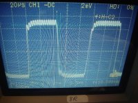
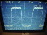
Attached the screen shots with 1:10 probes.
Picture 1&2
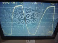
Up to 25Vpp rectangles are reproduced blameless into all load impedances.
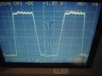
Picture 3&4
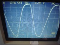
At 60Vpp the 2R is still driven blameless, but with 8R the overshoot is obvious.
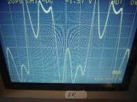
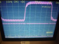
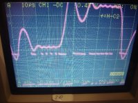
Picture 5&6
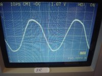
Trying to reproduce a rectangle with 114Vpp the 2R situation has no overshoot, but the rise time has increased due to the fundamental limitations that we get from the filter and available rail voltage.
This 114Vpp with a 10kHz rectangle is close to the shut down of the used power supply, note that the amp delivers already about 1.5kW in this situation.
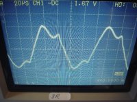
Pushing the amp with 8R to such levels of rectangular signals is resulting in massive overshoots, but still working in a controlled way.
THD, IMD, output filter/ fs/ carrier residuals at the output, step response.
It is my taste to balance them all in moderate way, without excessively focussing on just one property and ignoring all the rest.
I already have posted the THD, IMD and carrier residuals earlier, here the reproduction of rectangular signals.
At low and medium signal levels the rectangular reproduction is fast and blameless.
Limitations become visible only at large rectangles, which are not part of music program.
Despite being not part of music program also the CD format is not capable to deliver such signals, but for amp testing it is important to understand the limitations.
To speed up and catch back the filter fast, theory tells that the drive in front of the filter has to provide voltages which which are far larger (in both directions) then the filter output. Naturally the voltage that you can provide to the filter is limited by the supply rail of the amp. Means at high output levels there is no way to provide the theoretically needed huge signals at the filter input and consequently overshoots will happen – so you can chose to have the system generally slower, or fast and blameless at lower levels but with overshoot high levels with high load impedances.
Low load impedances will dampen the filter and avoid overshoot even at high levels.
Attached the screen shots with 1:10 probes.
Picture 1&2
Up to 25Vpp rectangles are reproduced blameless into all load impedances.
Picture 3&4
At 60Vpp the 2R is still driven blameless, but with 8R the overshoot is obvious.
Picture 5&6
Trying to reproduce a rectangle with 114Vpp the 2R situation has no overshoot, but the rise time has increased due to the fundamental limitations that we get from the filter and available rail voltage.
This 114Vpp with a 10kHz rectangle is close to the shut down of the used power supply, note that the amp delivers already about 1.5kW in this situation.
Pushing the amp with 8R to such levels of rectangular signals is resulting in massive overshoots, but still working in a controlled way.
Attachments
Hi Vilmar,
I am not sure what you are trying...
a) Asking me to do a custom design for you?
or
b) Offering to disclose your designs?
or
c) Selling your designs?
In case of a) we should check by PM.
In case of b) you should open a thread and show your designs.
In case of c) you should open a thread in the commercial section.
The rails are pretty stable at high load impedances.
Different from what the people tell who want to sell you their scrap,
it is fact that all class D amps with such LC output filters do suffer in both directions.
Only at one load impedance the filter does something acceptable.
At higher load impedances the filter generates overshot and ringing.
At lower load impedances the filter will show slower and slower creeping of the signal. This can be catched by postfilter feedback.
The shown amp has a postfilter feedback with PID loop gain which is capable to speed up the step response about factor three vs the natural step response of the filter.
Furtheron this PID loop is free of overshoot at 2R up to no load as long as the transfer chain remains linear.
Different from what most control theory books make us believe, most real chains are nonlinear and have hard limits like supply rails. In order to avoid brute destructive oscillation modes you have to limit the action of the I portion during such internal clipping situations (have a look to Q205 and Q206). With this only uncritical overshoots are happening in load situations which cause pre filter clipping.
And even this could be fully avoided by adjusting the PID loop in a way that the rise time would end up around 8...10us.
Rise times around 10us are pretty slow for high quality audio and bear the danger to cover small fast nuances of the music. At the same time it is pretty obvious that no music is made of full amplitude rectangles. For this reason I am convinced that this adjustment is by far more musical than an adjustment which has a 10us rise time.
Regarding most class D amps in the market - you will find that most of them come along with rise times around 10us or longer and still show overshoot at most loads and even at low signal levels...
They just don't tell it to anybody and hope nobody knows how to use a scope.
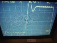
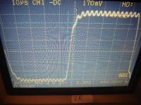
Below two comprehensive screen shots.
Upper trace is the output signal with 8R load. Lower trace is the signal at the filter input.
This signal contains the information about the rail and the PWM.
Obviously the rails are stable.
In the first picture you see that the PWM is always pulsing and the PID loop can perfectly control the filter.
In the second picture you see that there are long times were the PWM is not pulsing any more but giving full power to speed up the filter and to catch back the over. Very clear pre filter clipping.
You also see that the PWM is switching to the opposite direction already before the output has reached the intended value. In order to avoid the overshoot you would need to shift this even earlier,
which means larger D portion in the feedback and slower step response.
All measurements with 1:10 probes.
P.S.
Group buy? I did not intend a group buy. I am a silly tech soul who has no idea about logistics.
But in special cases I can give support with one or the other component.
In any case I should prepare the builders package (schematics, BOM, PCB data, some hints) first and also for this I have to ask for patience.
Different from what the people tell who want to sell you their scrap,
it is fact that all class D amps with such LC output filters do suffer in both directions.
Only at one load impedance the filter does something acceptable.
At higher load impedances the filter generates overshot and ringing.
At lower load impedances the filter will show slower and slower creeping of the signal. This can be catched by postfilter feedback.
The shown amp has a postfilter feedback with PID loop gain which is capable to speed up the step response about factor three vs the natural step response of the filter.
Furtheron this PID loop is free of overshoot at 2R up to no load as long as the transfer chain remains linear.
Different from what most control theory books make us believe, most real chains are nonlinear and have hard limits like supply rails. In order to avoid brute destructive oscillation modes you have to limit the action of the I portion during such internal clipping situations (have a look to Q205 and Q206). With this only uncritical overshoots are happening in load situations which cause pre filter clipping.
And even this could be fully avoided by adjusting the PID loop in a way that the rise time would end up around 8...10us.
Rise times around 10us are pretty slow for high quality audio and bear the danger to cover small fast nuances of the music. At the same time it is pretty obvious that no music is made of full amplitude rectangles. For this reason I am convinced that this adjustment is by far more musical than an adjustment which has a 10us rise time.
Regarding most class D amps in the market - you will find that most of them come along with rise times around 10us or longer and still show overshoot at most loads and even at low signal levels...
They just don't tell it to anybody and hope nobody knows how to use a scope.
Below two comprehensive screen shots.
Upper trace is the output signal with 8R load. Lower trace is the signal at the filter input.
This signal contains the information about the rail and the PWM.
Obviously the rails are stable.
In the first picture you see that the PWM is always pulsing and the PID loop can perfectly control the filter.
In the second picture you see that there are long times were the PWM is not pulsing any more but giving full power to speed up the filter and to catch back the over. Very clear pre filter clipping.
You also see that the PWM is switching to the opposite direction already before the output has reached the intended value. In order to avoid the overshoot you would need to shift this even earlier,
which means larger D portion in the feedback and slower step response.
All measurements with 1:10 probes.
P.S.
Group buy? I did not intend a group buy. I am a silly tech soul who has no idea about logistics.
But in special cases I can give support with one or the other component.
In any case I should prepare the builders package (schematics, BOM, PCB data, some hints) first and also for this I have to ask for patience.
Attachments
Last edited:
All shown measurements were done with the Hypex SMPS1200A700.
It is delivering +/- 83V during idle situation and is stiff enough to allow the amp to deliver about 1200W sinewaves into 2R.
Edit:
When you drive the amp into heavy clipping with 2R load, then the SMPS is shutting down at about 1.5kW.
IMHO for professional applications this SMPS is only making sense if you use a limiter, which avoids heavy clipping.
Last edited:
All shown measurements were done with the Hypex SMPS1200A700.
It is delivering +/- 83V during idle situation and is stiff enough to allow the amp to deliver about 1200W sinewaves into 2R.
Edit:
When you drive the amp into heavy clipping with 2R load, then the SMPS is shutting down at about 1.5kW.
IMHO for professional applications this SMPS is only making sense if you use a limiter, which avoids heavy clipping.
You using a Hypex SMPS1200A700
nice.. do you use this as your bench powersupply.JSP Page
sigh
its like 150 Euro Thats = 150 * 11.67 = R1750.5 anyone here know of a cheaper type sypply with the same quality and specification ?
-Overvoltage protection is fine.
-Over current protection is shutting down at 40A, here still a lot of work ahead to verify the worst case situation in detail and adjust to 50A and verify that...
-With respect to Tom's question, here the measurements regarding the damping factor.
I used a traditional solid state amp and a low inductive resistor to feed sine waves with 20App into the output of the class D amp and kept the input of the class D amp shorted.
@20App
20Hz: Voltage impact on D amp = 27mVpp, Ri= 1.35mOhms, ==> 2R damping factor = 1481
50Hz: Voltage impact on D amp = 28mVpp, Ri= 1.4mOhms, ==> 2R damping factor = 1429
100Hz: Voltage impact on D amp = 28mVpp, Ri= 1.4mOhms, ==> 2R damping factor = 1429
200Hz: Voltage impact on D amp = 28mVpp, Ri= 1.4mOhms, ==> 2R damping factor = 1429
500Hz: Voltage impact on D amp = 27mVpp, Ri= 1.4mOhms, ==> 2R damping factor = 1481
1kHz: Voltage impact on D amp = 20mVpp, Ri= 1mOhms, ==> 2R damping factor = 2000
2kHz: Voltage impact on D amp = 40mVpp, Ri= 2mOhms, ==> 2R damping factor = 1000
5kHz: Voltage impact on D amp = 97mVpp, Ri= 4.85mOhms, ==> 2R damping factor = 412
10kHz: Voltage impact on D amp = 206mVpp, Ri= 10.3mOhms, ==> 2R damping factor =194
20kHz: Voltage impact on D amp = 533mVpp, Ri= 26.7mOhms, ==> 2R damping factor =75
...right - I also wondered about that and double checked the measurements and got identical readings.
But we have to consider that the output impedance is extremely low.
On purpose I showed the 2R damping factors, while normal marketing strategy would be to show the 8R damping factor only at 1kHz - which is 8000
Cool number, but perfectly meaningless.
Anyway, when measuring such low output impedances already the magnetic field of the load wires can easily induce signals to the input of the amp which lead to output signals larger than the signal you want to measure.
Even with optimized wire geometries there will be fields which induce into the amp input. Also fields from its internal layout tracks and voltage drops in the GND plane influence the damping factor.
- Home
- Amplifiers
- Class D
- SystemD_2kW, any interest for an open design?