I was once foolish enough to use paralleled X7R SMD caps as the output filter, in a low power (30W) UCD-style amp. Even though there were 4 caps in parallel and post-filter nfb, the measured distortion was over 3 times high than with film caps.
I eventually tried 100 X 0.01uF/500V X7Rs once for the filter, but the distortion was still higher than pair of film capacitors.

@Workhorse:
Yes. Ignorance is a bliss. Also for me.
Sometimes the only way to stay mentally stable.
@Vaclav:
Distortion of COG in signal paths can be expected to be low.
Despite that there are people who say COG sounds harsh - I never tried and have no evidence whether I would perceive it also this way or if I should call it a myth.
In any case the offer on the farnell page is looking like a typo to me.
COG with 330nF/100V in this size is really far beyond what I would expect from today's COG technology.
Both MBR7030 avoid that the body diodes will be flooded.
The question about body diodes is one of the oldest in classD and always a hot discussion up to which power level at which switching frequencies it is making sense to use them.
Simulation showed that in this project the IRFP4668 would struggle hard with its body diodes.
Vienna Tom and Workhorse pointed out that already top brands had tried to go this path, but had issues with reliability.
So I stepped into manual calculation and noticed that the simulation was misleading in a forgiving way.
Altogether a clear indication to spend the additional components.
I have chosen a low amount of SMD components, because many DIYers complain about SMD. So this design is a trade off.
Intended for high performance, high power - still DIYable for experienced enthusiasts who like the design.
Of course not a beginner project, because of it's complexity and involved high voltages.
In case you want to build it, please wait until the design is ready and has reached a sufficient level of maturity.
If you read this thread from the beginning you will find the evolution and many design considerations.
As far as I can see, it seems that Hypex has gone down same path as you with both UcD700 and UcD2K (2k also using diodes in TO220 and MOS in TO247). I'm still wondering on how far you can go without extra diodes, using MOS like IRFB5620. I would guess something like 500W@8R is the limit.
Baldin
It is a question of switching frequency and desired reliability....
If one just heading for 'It can work.' - then almost any promise is possible.
The limiting parameter typically is not the gate charge, but Qrr and max. power dissipation of the MosFets. So also the famous IRFB4227 are coming into the race as well.
500W into 8R from a halfbridge with 200V devices is beyond my taste in any case, already from the required rail voltage.
Year maybe 500W@8R is a bit too high for 200V devices ... say 400W@8R.
Yes IRFB4227 is a very good choise.
For something like 250W@8R at 250kHz I was planning on using ES3D as freewheeling diodes. They have excellent trr and can take 100A peak. They are only 3A, but my initial simulations show less then 2A RMS (at 60V rails and switching into 4R)
Was looking at your calculations in post #109 ..... not sure how you come to up to 500W in losses per device ..... at 2KW I wouldn't think total osses would exceed 10% = 200W
Hi Baldin,
I see you are interested in analysing switching losses.
So prepared a detailed manual calculation - more detailed than what I did earlier.
*lol* The more details the worse the result.
Already the turn ON losses of the IRFP4668 under hard switching of 60A with 300kHz and 164V rails sum up to 510W.
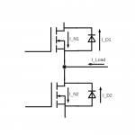
The graphs are showing the current commutation from upper body diode to the N chanel of the lower MosFet, when current is running from the filter into the half bridge.
Please note that I assumed DC load, which is more tough than reality, because music signals are not DC, but more like sine modulated and intermitting... consequently of course the avarage losses with music program are by far less.
Nevertheless during a massive bass attack the MosFet will see such loads repetitively for durations of multiple full ms.
Turning ON
I_D1: Current through body diode of upper MosFet
I_D2: Current through body diode of lower MosFet
I_N1: Current through N chanel of upper MosFet
I_N2: Current through N chanel of lower MosFet
I_load: Current delivered from the filter choke
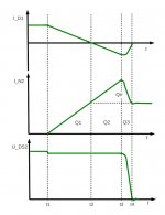
I_RRM: Reverse recovery peak
Qrr: Reverse recovery charge
t1: At this point in time Ugs of the lower MosFet is being pulled up above its threshold voltage.
t2: Now the current in the lower MosFet equals I_load.
t3: The reverse recovery reaches its peak and diode snap back begins
t4: Qrr is fully removed.
Numbers with IRFP4668 in this project:
Intended load currents up to 60A.
Qrr @ 125C and di/dt=800 A/us: 3600nC
I_RRM @ 125C and di/dt=800 A/us: 55A
Calculating t2-t1 and Q1:
t2-t1 = 60A/800 A/us = 75ns
Q1 = 0.5* 60A * 75ns = 2250nC
Calculating t3-t2 and t4-t3 and Q2:
t3-t2 = 55A/800 A/us = 69ns
First portion of Qrr while t2<t<t3: 0.5* 55A * 69ns = 1900nC
Second portion of Qrr t3<t<t4: 3600nC-1900nC= 1700nC
t4-t3 = 1700ns/1900ns*(t3-t2)= 62ns
Q2= (t3-t2)*60A = 4140nC
Q3= (t4-t3)*60A = 3720nC
Energies:
The small step of U_DS2 is an inductive drop. Typically few volts.
For loss calculation I am typically neglecting it.
Until t3 U_DS2 remains almost at full rail level = 164V.
While t3<t<t4 U_DS2 is sloping down, simplified averaged value is half the rail = 82V.
W_ON1= (Q1+Q2+firstportionofQrr) * U_DS2 = 8290nC*164V = 1.36J
W_ON2= (Q3+secondportionofQrr)*U_DS2 = 5420nC*82V = 0.44J
W_ON=W_ON1+W_ON2=1.7J
P_ON= W_ON*fs=1.7J*300kHz= 510W
...it is definitely no wonder that such use will lead to short comings in reliability.
Who volunteers to prepare the turn OFF losses in a similar way?
Don't panic they are less and simpler.
And here the overview of options to improve things.
a) Avoiding to flood the body diodes by optimized dead time (overlap).
This needs a MosFet with a low R_DSON. At 125C you have to keep the voltage drop across the N chanel lower than the forward voltage of the body diode. Means you have to keep the drop below 300...400mV.
For IRFP4668 you will reach this limit between 15A..20A.
b) Avoiding to flood the body diodes by optimized dead time and paralleling free wheeling shottkys.
Current will share the paths of the N chanel and the shottky.
Depending on your choice of shottky you can lift the possible currents without flooding the body diode by another 10-20A. IMHO up to 30A it would be worth to try.
c) Avoiding to flood the body diodes by a series shottky and freewheeling diode.
That's what I decided to do.
d) GaN
e) SiC
I see you are interested in analysing switching losses.
So prepared a detailed manual calculation - more detailed than what I did earlier.
*lol* The more details the worse the result.
Already the turn ON losses of the IRFP4668 under hard switching of 60A with 300kHz and 164V rails sum up to 510W.
The graphs are showing the current commutation from upper body diode to the N chanel of the lower MosFet, when current is running from the filter into the half bridge.
Please note that I assumed DC load, which is more tough than reality, because music signals are not DC, but more like sine modulated and intermitting... consequently of course the avarage losses with music program are by far less.
Nevertheless during a massive bass attack the MosFet will see such loads repetitively for durations of multiple full ms.
Turning ON
I_D1: Current through body diode of upper MosFet
I_D2: Current through body diode of lower MosFet
I_N1: Current through N chanel of upper MosFet
I_N2: Current through N chanel of lower MosFet
I_load: Current delivered from the filter choke
I_RRM: Reverse recovery peak
Qrr: Reverse recovery charge
t1: At this point in time Ugs of the lower MosFet is being pulled up above its threshold voltage.
t2: Now the current in the lower MosFet equals I_load.
t3: The reverse recovery reaches its peak and diode snap back begins
t4: Qrr is fully removed.
Numbers with IRFP4668 in this project:
Intended load currents up to 60A.
Qrr @ 125C and di/dt=800 A/us: 3600nC
I_RRM @ 125C and di/dt=800 A/us: 55A
Calculating t2-t1 and Q1:
t2-t1 = 60A/800 A/us = 75ns
Q1 = 0.5* 60A * 75ns = 2250nC
Calculating t3-t2 and t4-t3 and Q2:
t3-t2 = 55A/800 A/us = 69ns
First portion of Qrr while t2<t<t3: 0.5* 55A * 69ns = 1900nC
Second portion of Qrr t3<t<t4: 3600nC-1900nC= 1700nC
t4-t3 = 1700ns/1900ns*(t3-t2)= 62ns
Q2= (t3-t2)*60A = 4140nC
Q3= (t4-t3)*60A = 3720nC
Energies:
The small step of U_DS2 is an inductive drop. Typically few volts.
For loss calculation I am typically neglecting it.
Until t3 U_DS2 remains almost at full rail level = 164V.
While t3<t<t4 U_DS2 is sloping down, simplified averaged value is half the rail = 82V.
W_ON1= (Q1+Q2+firstportionofQrr) * U_DS2 = 8290nC*164V = 1.36J
W_ON2= (Q3+secondportionofQrr)*U_DS2 = 5420nC*82V = 0.44J
W_ON=W_ON1+W_ON2=1.7J
P_ON= W_ON*fs=1.7J*300kHz= 510W
...it is definitely no wonder that such use will lead to short comings in reliability.
Who volunteers to prepare the turn OFF losses in a similar way?
Don't panic they are less and simpler.
And here the overview of options to improve things.
a) Avoiding to flood the body diodes by optimized dead time (overlap).
This needs a MosFet with a low R_DSON. At 125C you have to keep the voltage drop across the N chanel lower than the forward voltage of the body diode. Means you have to keep the drop below 300...400mV.
For IRFP4668 you will reach this limit between 15A..20A.
b) Avoiding to flood the body diodes by optimized dead time and paralleling free wheeling shottkys.
Current will share the paths of the N chanel and the shottky.
Depending on your choice of shottky you can lift the possible currents without flooding the body diode by another 10-20A. IMHO up to 30A it would be worth to try.
c) Avoiding to flood the body diodes by a series shottky and freewheeling diode.
That's what I decided to do.
d) GaN
e) SiC
Attachments
Thanks to the calculation and explanation.
Hmmm, not sure I understand and my common sense says that you are not going to burn 500W in each mosfet in real life, with 2KW out (that would be very low efficiency)..... and at 500W the devices will die of heat anyway
Don't know why you use 60A for your calculations. @2R we are talking around 40A max ... right (but maybe you intend to go higher than 2KW ~ Rload<2ohm)
Not sure I understand "assumed DC load" ... do you mean hard clipping ... in that case I think the switching losses will get less, as you will have less switching points per periode ... and therefore can't in that case multiply by the switching frequency to summ up the losses (as there will be way less than 300.000 er second).
Kind regards Baldin
Hi Baldin,
60A are for headroom in case of impedance drops.
The load situation is not hard clipping. As you say, hard clipping is easy going for the power devices as long as the modulator and dead time circuit and HF resonances are solved correctly.
Background for load situation.
A 20Hz bass with high output voltage close to clipping.
The speaker are driven below resonance and their impedance will be close to Rdc.
Instead of 2R you can easily have below 1.5R.
Now zoom into the max during negative half wave.
The amp is pulling the hot speaker wire towards negative.
Say output voltage is -75V, output current is i.e. -55A.
The switching frequency is so much higher vs the frequency of the load current, that the load current can be regarded as DC. For a 20Hz signal you can easily aproximate the load current as stepped DC values for a duration of 2ms each step.
Let's look at the situation during neg max again.
In this moment the upper MosFet does not make much losses.
The instantanous power in this load situation is 4125W.
p(t) = Umax*sin (wt) * Imax*sin(wt) in case of sinusodial signal and resistive load.
Why do poorly designed amps survive in most cases?
Typically the selfoscilating amps reduce fs towards high modulation, this also helps for efficiency. Also the fact that this load is not happening continously helps.
Why do I calculate with the high fs?
Imagine a short (i.e. 0.05R) with a signal that drives the circuit close to overcurrent shut down - in this case you will have the high currents and high frequency.
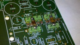
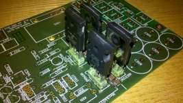
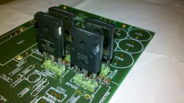
The PCB has arrived.
Attached two pictures which show the 'third layer' - the CuBar connection between series diodes and MosFet drains.
The double pin rows are intended to comfort the leads of the TO247 with low inductance and at keep the design serviceable.
Attached two pictures which show the 'third layer' - the CuBar connection between series diodes and MosFet drains.
The double pin rows are intended to comfort the leads of the TO247 with low inductance and at keep the design serviceable.
Attachments

@Reactance:
I am afraid - I have to assemble and debug it first.
But then I will post some screen shots as well.
@Effebi:
My first choice is a T157-2.
But I have given enough space in the PCB to comfort a large gapped ferrite E-core.
Most ferrite E-cores which offer an Ae around 200mm² should allow a useable solution.
In case you seriously consider to built the amp and have a specific core on hands we can go through the design procedure.
Please note, if you use a gapped E-core you should use HF-litz or at least DIY-multistranded, not a solid wire.
@ Choco just FYI:
Today I had a meeting with guys from PowerInt (actually guys from Munich!). There is an upcoming 200V "Q-speed" diode series: 20, 30, 40 Amps. Unfortunately I can't find the specific 200V parts at their website.
Qspeed Family of Advanced Diodes | Power Integrations
Today I had a meeting with guys from PowerInt (actually guys from Munich!). There is an upcoming 200V "Q-speed" diode series: 20, 30, 40 Amps. Unfortunately I can't find the specific 200V parts at their website.
Qspeed Family of Advanced Diodes | Power Integrations
Last edited by a moderator:
Thanks for the link, Tom.
Already the existing LQA60A300C
http://www.powerint.com/sites/default/files/product-docs/lqa60a300c.pdf
is a beauty.
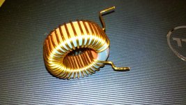
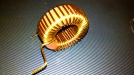
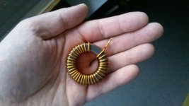
..and to keep the readers happy until my proto goes on... -some pictures of my preferred output choke.
T157-2 with 33turns (most likely I will reduce it to 32 turns).
Solid wire of 1.32mm diameter.
I am offering to support other custom choke designs with gapped ferrites and multistranded twisted wires on request.
Already the existing LQA60A300C
http://www.powerint.com/sites/default/files/product-docs/lqa60a300c.pdf
is a beauty.
..and to keep the readers happy until my proto goes on... -some pictures of my preferred output choke.
T157-2 with 33turns (most likely I will reduce it to 32 turns).
Solid wire of 1.32mm diameter.
I am offering to support other custom choke designs with gapped ferrites and multistranded twisted wires on request.
Attachments
- Home
- Amplifiers
- Class D
- SystemD_2kW, any interest for an open design?