...also thinking about the emitter switched approach.
The unpleasant thing is that ST starts its portfolio at 1700V and the most types have higher Rdson... Not the right thing for a 200V application.
Hm, discrete solution for emitter switched?
Ugh - component count. Mr. Nitpicker is back
On the other hand, the MosFet will be a low voltage type with low gate charge
and could be driven directly from the IRS20957, without additional totem pole driver.
Did Workhorse say 'tempting'??? ...have to dig deeper...
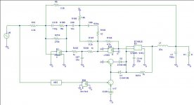
I still owe you the other modulation variant. Here it is. Instead of Multiplying the fed-back voltage (which is deterimining the hysteresis) in some way or applying clamping somewhere in the voltage divider the hysteresis can be set solely by clamping form the beginning. Simulated performance is almost as good as the version with multiplier. The gain of E89 was set to 0.35. BTW: C314 is there to guarantee convergence of SPICE (also the other variants had this) it is not needed in a real-life circuit.
Regards
Charles
Regards
Charles
Attachments
I have the feeling that the emitter switched approach is coming to a dead end for our application from very fundamental considerations.
- It is hard to find 200V/50A type. Especially when interested in reasonably fast types and high current gain.
- Even when considering to parallel three (ugh!!) of the famous 2SC2922 at 50A we would get a current gain around 20 (blue eyed without considering frequency).
With that we would need to feed 2.5A base current. No fun.
...even if averaging this over music program, we will still end up in something like 500mA. Not promising for a boot strapped floating high side supply.
In case you find 200V-BJTs which can handle 50A in a single device and provide a current gain of >50 at 50A, then it could become a viable option.
Please don't hesitate to post your findings.
The idea is really tempting, except that I am not aware of fitting real world devices.
Overall these considerations fit to the fact that ST is using this technology only at high voltage, where MosFet technology is a pure catastrophy.
.... the hysteresis can be set solely by clamping ....
I definitely like your new approach.
The extreme dv/dt > 10kV/us are IMHO related to the high Qrr and sudden current snap back of the diode as soon as the Qrr is removed.
During removing Qrr at output currents of 50A the current through the MosFet is ramping up to more than 100A (50A for the load and more than 50A to feed the recovery peak of the opposite body diode recovery peak). When Qrr is removed the body diode snaps back and drops current with di/dt of multiple kA/us. Means suddenly there are more than 50A unneeded current stored in the parasitic inductances, which deliver this current to the parasitic capacitances without any delay, resulting in unsaint dv/dt.
I case of low Qrr and soft recovery or mostly capacitive behavior like shottkys, such excessive dv/dt are not likely.
Freewheling
V30200C is back in the race
HFB35HB20 also promising
STTH3002C another candidate
For series shottky I defintely like the
60CTTN015
but it should be easy to find multiple suitable types.
Any comments or real life experiences on this?
Further diode proposals?
Agree...HFB35HB20 and STTH3002 IMHO can not compete to V30200C.
IRFP4668 with diodes appears more preferably to me, because it is more forgiving regarding dead time and idle losses.For shunting the body diode, you may also try 2 x IPP110N20N3 (and no diodes) instead 1 x 4668 plus diodes.
The shunting method only works with really precise dead time adjustment and all my experiments with that where fitting to theory which tells me that you have to adjust to remarkable cross conduction during idle in order to minimize charge transfer to the body diode in the switching moment at high currents.
It is possible, but again no lunch for free
Already used cascoded emiter design for over 12 years in my amplifier... Now I use 2// BSC059N04LSG lo voltage device, with 2// HGTG20N60A4D IGBT high voltage device and APT30D60BHB freewheeling device... Only way I found to run amp at more than +/-100v... At +-/250V, I got 6Kw into 4 ohms... No way to go to 2 ohms... Simple 6N137/TC4421 driver.
Hey guys since I have no other source of Internet other than my iPhone I will keep this post short. Have you considered a neutral point clamped half bridge. I have used this topology many times in high frequency (20kHz+) motor drive designs in the >100kW range with 900V busses and 600V IGBT modules. It would allow you to use 120V(20% margin) devices in +/- 100V applications, however your modulator will become more complicated. It is much more suited to triangle based modulators.... Will give more thought to hysteresis modulation and this output topology.
Let's stay with the +/-80V level (say below +/-100V) .
Running such an amplifier bridged and stereo at full power will already cause visible fluctuations of the light in a normal house - if not already tripping the mains breaker...
In my flat I already saw the light changing when testing load steps of my last smps design, which was just 1.3kW.
With the intended design we would already be at the level of pulsating 4-5kW.
Both topologies (emitter switched and NPC) definitely have a better fit to higher voltages.
Of course one can build a NPC halfbridge for +/-80V, but I think the efforts especially for the three floating gate drives would definitely kill the goal to keep the design DIYable and remote debugable. Don't you think so?

"In my flat I already saw the light changing when testing load steps of my last smps design, which was just 1.3kW.
"
Light bulbs are very sensitive to small RMS voltage flicker. And the eye is very sensitive to small light changes. At 230VRMS, even 1V flicker can be visible, while +/-10 V changes would still be ok with most AC connected equipment..
I am not sure what your 2kW amp application is within your flat and if all your neighbours would like to dance to your special music ;-) but to avoid flicker, you may just choose a different AC phase for your amplifiers than for lighting.
...I was just joking about my flat. In fact there alread my 60W rookie amps driving my 86db/W mini speakers are more than my neighbours can take
I am thinking more about the flicker standard DIN EN 61000-3-3.
There is a flicker curve given, which tells the max. allowed change of the mains voltage as a function of voltage changes per minute.
This curve was derived empirical with a large group of students as test persons. It describes the limit of voltage change which becomes visible when feeding a 60W light bulb.
Every drum beat will cause such a voltage change. Assuming 110 beats/minute the allowed voltage change is around 0.7%.
A mains which is stiff enough to change not more than 0.7% when beeing loaded with pulsating 4-5kW (stereo 2x2kW plus losses), is already beyond average.
I think 2kW (or may be 2.4kW) is a nice number for a high power DIY project. I am definitely not intending to push it higher.
Back to circuit design:
For the simple configuration of just two MosFets I am using since years a simulation model which includes the relevant parasitics. Fit between sim and reality was not perfect, but good.
I extended the sim model to the circuitry with series shottky and additional freewheeling diode.
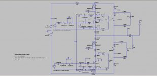
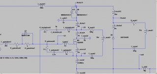
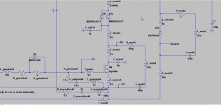
Attached a screen shot of the model and two zooms - showing high side and low side more detailed.
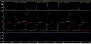
When using reasonably good freewheling diodes I am getting a mostly calm behavior. Even without any snubbering the wave forms remain good enough that the circuit should still work somehow.
The attached wave forms are showing the situation with the values of the shown schematics.
Means snubbering at the gates and across the freewheling diodes, but no snubbering at the MosFets. Also I put 2uF caps from the drain of the upper MosFet to the source of the lower MosFet, while the 100nH inductors model the wiring towards the e-caps and e-cap inductance.
Which real life experiences do exist? Is the configuration with series shottkys and fast soft recovery freewheeling diodes really that forgiving as shown in the sim? Please note, it shows the situation of 50A hard switching, not idle.
...have to check for a sim model of the V30200, from my understanding this diode should make the system even more calm...
For the simple configuration of just two MosFets I am using since years a simulation model which includes the relevant parasitics. Fit between sim and reality was not perfect, but good.
I extended the sim model to the circuitry with series shottky and additional freewheeling diode.
Attached a screen shot of the model and two zooms - showing high side and low side more detailed.
When using reasonably good freewheling diodes I am getting a mostly calm behavior. Even without any snubbering the wave forms remain good enough that the circuit should still work somehow.
The attached wave forms are showing the situation with the values of the shown schematics.
Means snubbering at the gates and across the freewheling diodes, but no snubbering at the MosFets. Also I put 2uF caps from the drain of the upper MosFet to the source of the lower MosFet, while the 100nH inductors model the wiring towards the e-caps and e-cap inductance.
Which real life experiences do exist? Is the configuration with series shottkys and fast soft recovery freewheeling diodes really that forgiving as shown in the sim? Please note, it shows the situation of 50A hard switching, not idle.
...have to check for a sim model of the V30200, from my understanding this diode should make the system even more calm...
Attachments
- Home
- Amplifiers
- Class D
- SystemD_2kW, any interest for an open design?